USE ONLY HAYWARD GENUINE REPLACEMENT PARTS
11
Maintenance
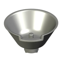
Step 1: Use a 1¼” socket bit to remove the Laminar Jet cap to access screens. Remove the
union on the bottom to access diffusers.
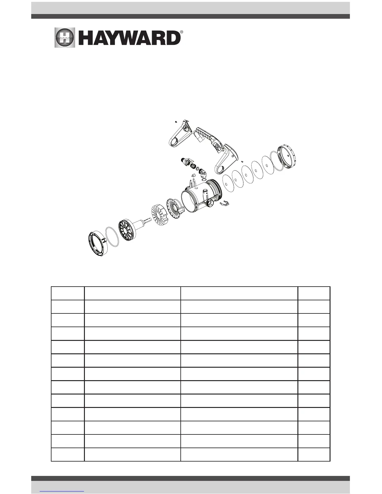
Step 2: Remove any debris that may have been captured during operation. Refer to the diagram
below for disassembly and maintenance. NOTE: O-rings should be re-lubricated as
needed.
Replacement Parts
ITEM PART NUMBER DESCRIPTION QTY
1 GLXWFLLIDGRY LIGHT GREY LID, DECK NICHE 1
2 GLXWFLLIDDKGRY DARK GREY LID, DECK NICHE 1
3 GLXWFLJET LAMINAR JET 1
4 GLXWFLHOSE WATER INLET ASSEMBLY 1
5 GLXWFLOPTC OPTIC BOTTOM SEAL PLATE 1
6 GLXWFLTUBE TUBING ASSEMBLY 1
7 GLXWFLDISRPT DISRUPTOR ASSEMBLY 1
8 GLXWFLLDSCRWPK10 DECK NICHE LID SCREW, 10PK 1
9 GLXWFLSCRNPK5 SCREEN, 5PK 1
10 GLXWFLGASKET LAMINAR GASKET KIT 1
11 GLXWFLVLVADPT VALVE ADAPTER KIT 1
12 GLXWFLTSPLT TOP SEAL PLATE 1
 Loading...