15
tected by a further main fuse located close to the
battery (max. distance from battery: 30 cm / 12”).
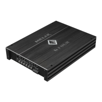
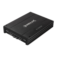
The HELIX G FOUR is equipped with 2 x 30 Am-
pere fuses.
15
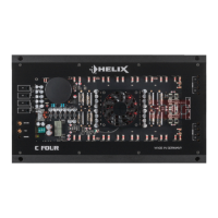
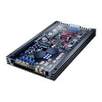
Power & Protect LED
The power and protect LED indicates the operating
mode of the amplier. The LED lights up green
when the amplier is ready for operation. If the LED
lights up red a malfunction has occurred.
A malfunction may have different causes as the
HELIX G FOUR is equipped with different protec-
tion circuits. These protections shut off the ampli-
er in case of overheating, over- and undervoltage,
short-circuit on loudspeakers and false connection.
Please check for connecting failures such as
short-circuits, wrong connections, wrong adjust-
ments and over temperature.
If the amplier does not turn on it is defective and
has to be send to your local authorized dealer for
repair service. A detailed description of the malfunc-
tion and the purchase receipt has to be attached.
16
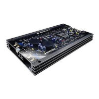
Output Channels
Speaker outputs of the channels A - D to con-
nect speaker systems. The impedance per chan-
nel should not be lower than 2 Ohms (4 Ohms in
bridged mode).
Installation
Connection of HELIX G FOUR to the head unit/
car radio:
Caution: Carrying out the following steps will re-
quire special tools and technical knowledge. In or-
der to avoid connection mistakes and / or damage,
ask your dealer for assistance if you have any ques-
tions and follow all instructions in this manual (see
page 11). It is recommended that this unit will be
installed by an authorized HELIX dealer.
1. Connecting the pre-amplier inputs
Use the correct cable (RCA / cinch cable) to
connect these inputs to the pre-amplier /
lowlev el / cinch outputs of your car radio. It is not
mandatory to use all pre-amplier inputs. If only
two channels will be connected we recommend
to use the channels A and B and set the Input
Mode switch to “2CH”. When all channels will
be used please choose switch position “4CH”
(see page 13 point 2; Input Mode). The auto-
matic turn-on circuit does not work when using
the pre-amplier inputs. In this case the remote
input (REM) has to be connected to activate the
HELIX G FOUR.
Important: It is strictly forbidden to use the
Highlevel Input and pre-amplier inputs (Line
Input) at the same time. This may cause severe
damage to the pre-amplier outputs of your car
radio.
2. Connecting the highlevel speaker inputs
The highlevel loudspeaker inputs can be con-
nected directly to the loudspeaker outputs of an
OEM or aftermarket radio using appropriate ca-
bles (loudspeaker cables with 1 mm² / AWG 18
max.).
We recommend the following channel assign-
ment:
Channel A = Front left
Channel B = Front right
Channel C = Rear left
Channel D = Rear right
Actually it is not mandatory to use all highlevel
speaker inputs. If only two channels will be con-
nected we recommend to use the channels A
and B and set the Input Mode switch to “2CH”.
When all channels will be used please choose
switch position “4CH” (see page 13 point 2; In-
put Mode).
Make sure that the polarity is correct. If one
or more connections have reversed polarity it
may affect the performance of the amplier. If
this input is used the remote input (REM) does
not need to be connected as the amplier will
automatically turn on once a loudspeaker signal
is applied.
3. Adjustment of the input sensitivity
Attention: It is mandatory to properly adapt
the input sensitivity of the G FOUR to the
 Loading...