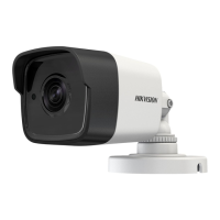
2.1 Installation of Type I Camera
2.1.1 Ceiling/Wall Mounting without Junction Box
Steps:
1. Paste the drill template (supplied) to the place
where you want to install the camera.
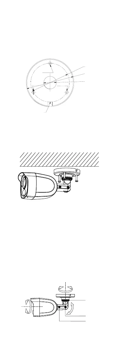
2. Drill the screw holes and the cable hole (optional) in
the ceiling/wall according to the drill template.
Figure 2-1 Drill Template
Note:
Drill the cable hole, when adopting the ceiling outlet
to route the cable.
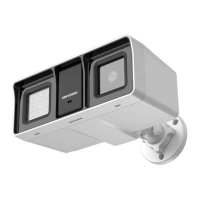
3. Attach the bracket to the ceiling/wall, and secure
the camera with supplied screws.
Figure 2-2 Fix the Camera to the Ceiling
Note:
The supplied screw package contains self-tapping
screws, and expansion bolts.
For cement wall/ceiling, expansion bolts are
required to fix the camera. For wooden
wall/ceiling, self-tapping screws are required.
4. Route the cables through the cable hole, or the side
opening.
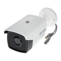
5. Connect the corresponding power cord, and video
cable.
6. Power on the camera to check whether the image
on the monitor is gotten from the optimum angle. If
not, adjust the camera according to the figure below
to get an optimum angle.
 Loading...