Quick Operation Guide of DS-7200-SH/SV/SL and DS-7300/8100-SH Series DVR
10
R- terminals of PTZ receiver respectively.
KB Connect the D+ and D- terminals to Ta and Tb terminals of the controller.
For cascading devices, the first DVR’s D+ and D- terminals should be
connected with the D+ and D- terminals of the next DVR.
11 Alarm In/Out Connector for alarm input/output.
12 eSATA Connects external SATA HDD, DVD-R/W.
13 100~240VAC 100~240VAC power supply.
14 POWER Switch for turning on/off the device.
15 GND Ground(needs to be connected when DVR starts up)
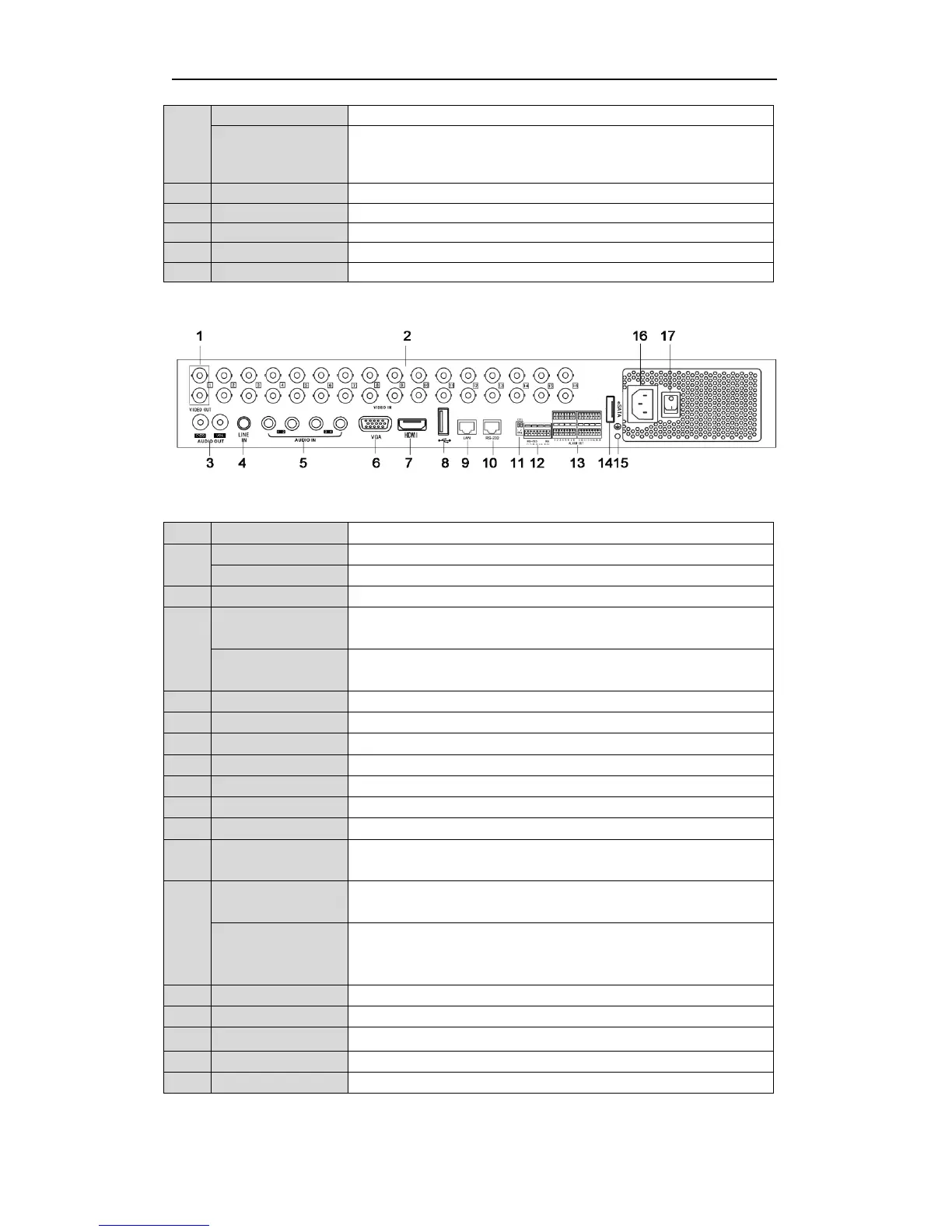
DS-7332HFI-SH, DS-7332HWI-SH and DS-7332HI-SH:
Note: The rear panel of DS-7324HFI-SH/DS-7324HWI-SH/DS-7324HI-SH provides 24 video input interfaces.
Table 7 Description of Rear Panel
BNC connector for video output.
BNC connector for spot video output.
2 VIDEO IN BNC connector for analog video input.
RCA connector for audio output. This connector is synchronized with CVBS
RCA connector for audio output. This connector is synchronized with VGA
4 LINE IN RCA connector for two-way audio input.
5 AUDIO IN RCA connector for audio input.
6 VGA DB15 connector for VGA output. Display local video output and menu.
7 HDMI HDMI video output.
Connects USB mouse or USB flash memory devices.
9 LAN Interface RJ45 10M / 100M / 1000M Ethernet interface.
10 RS-232 Connector for RS-232 devices.
RS-485 termination switch. Up position is not terminated.
Down is terminated with 120Ω resistance.
RS-485 Interface Connector for RS-485 devices. Connect the T+ and T- terminals to the R+
and R- terminals of PTZ receiver respectively.
KB Connect the D+ and D- terminals to Ta and Tb terminals of the controller.
For cascading devices, the first DVR’s D+ and D- terminals should be
connected with the D+ and D- terminals of the next DVR.
13 Alarm In/Out Connector for alarm input/output.
14 eSATA Connects external SATA HDD, DVD-R/W.
GND Ground(needs to be connected when DVR starts up)
16 100~240VAC 100~240VAC power supply.
17 POWER Switch for turning on/off the device.
 Loading...