Fingerprint and Card Reader User Manual
5
Chapter 2 Installation
2.1 Introduction for DIP Switch
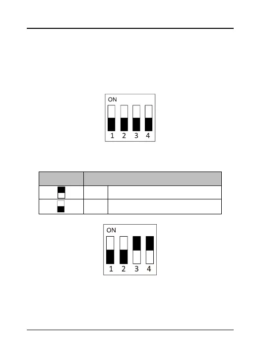
The DIP switch module is shown below. The No. of DIP switch from
left to right is 1 to 4, representing the RS-485 address.
Figure 2-1 DIP Switch Module
Table 1-2 Description of DIP Switch
Represent ON in binary mode
Represent OFF in binary mode
For example, the binary value of the following status is 1100.
Figure 2-2 DIP Switch Module
Note: The DIP switch of RS-485 address should reach the access
control devices requirements. For different access control devices,
the DIP switch addresses may be different.
 Loading...