EasyManuals Logo
Home>HIKVISION>Intercom System>DS-KB2421-IM

HIKVISION DS-KB2421-IM User Manual

HIKVISION DS-KB2421-IM
22 pages
To Next Page IconTo Next Page
To Previous Page IconTo Previous Page
Page #12 background imageLoading...
Page #12 background image
Video Door Phone User Manual
5
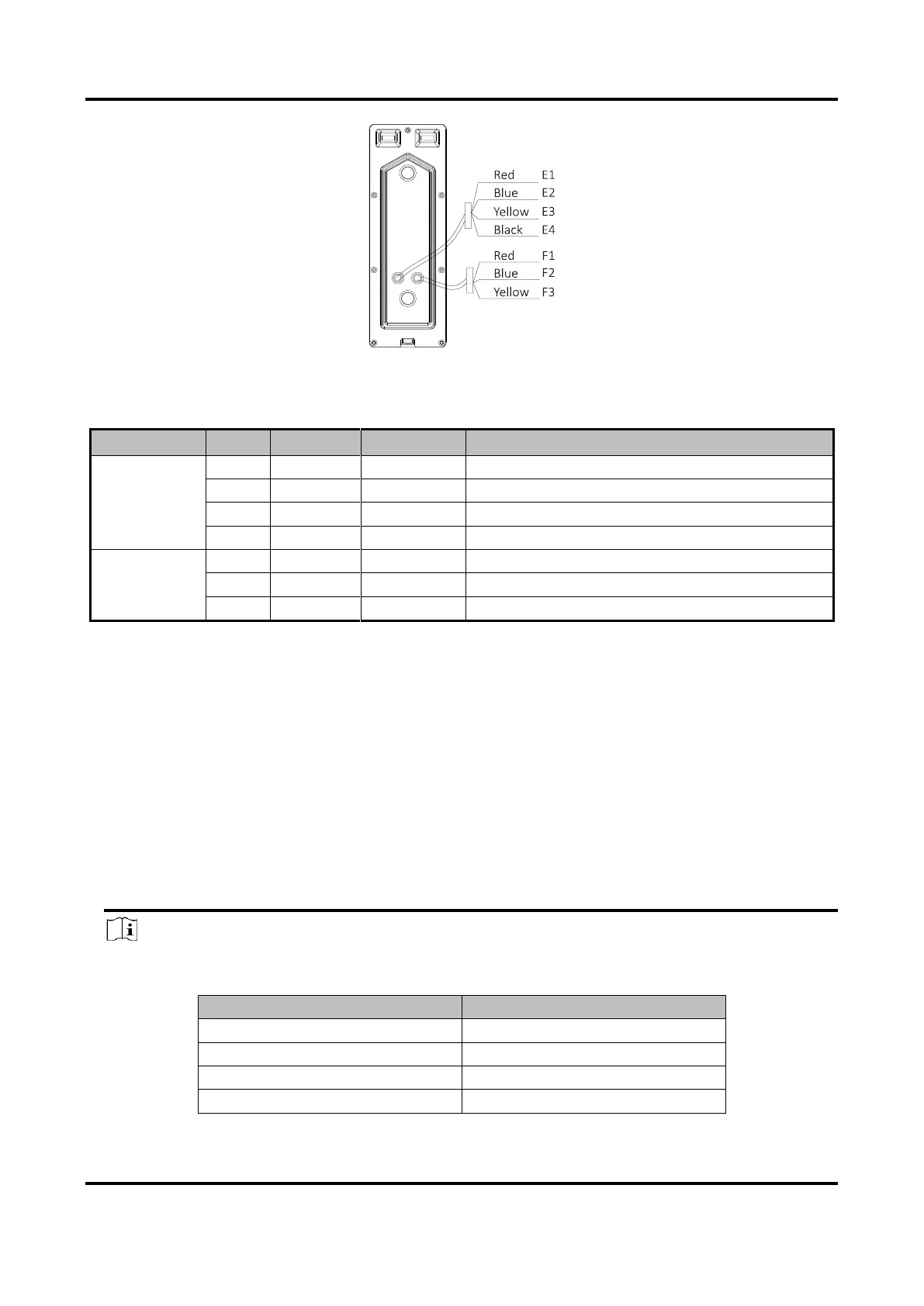
Figure 3-2 Wire of Door Station
Table 3-2 Descriptions of Terminals and Interfaces (Door Station)
Name
No.
Color
Interface
Description
Wire Group
(Four-Wire)
E1
Red
5V
Power Supply (from Indoor Station)
E2
Blue
CVBS
Video Output
E3
Yellow
AUIDO
Audio Input/Output
E4
Black
GND
Grounding Signal
Wire Group
(Lock)
F1
Red
NO
Door Lock Relay Output/Normally Open
F2
Blue
COM
Door Lock Relay Output/Common
F3
Yellow
NC
Door Lock Relay Output/Normally Closed
3.2 Wiring Description
Purpose:
The four-wire indoor station and the four-wire door station are 2 basic but major components in a
four-wire video intercom system. As for extended components, the analog camera and the electric
bolt can be connected to the indoor station and the door station respectively in a four-wire video
intercom system.
Up to 2 door stations are supported simultaneously in the intercom system.
Up to 3 indoor stations are supported simultaneously in the intercom system.
Here take 3 wirings as example.
Note
According to different transmission distances among door stations and indoor stations,
different RVV4 cable specifications are demanded.
Transmission Distance (TD)
RVV4 Cable Specification
TD 10 m
RVV4 * 0.2 mm ^2
10 m < TD 30 m
RVV4 * 0.5 mm ^2
30 m < TD 50 m
RVV4 * 0.75 mm ^2
50 m < TD 100 m
RVV4 * 1.5 mm ^2

Questions and Answers:

Question and Answer IconNeed help?

Do you have a question about the HIKVISION DS-KB2421-IM and is the answer not in the manual?

HIKVISION DS-KB2421-IM Specifications

General IconGeneral
BrandHIKVISION
ModelDS-KB2421-IM
CategoryIntercom System
LanguageEnglish

Related product manuals