Video Door Phone User Manual
9
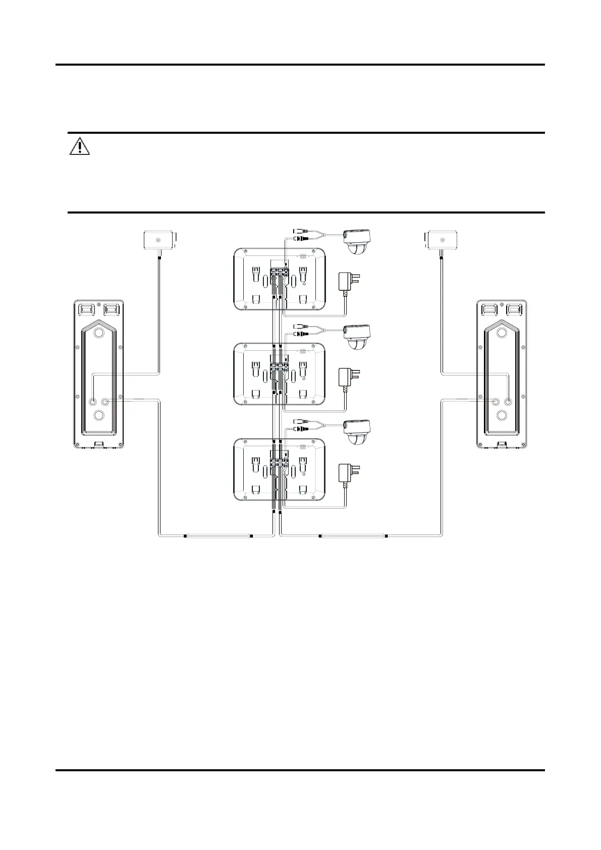
3.2.3 Wiring 3 (2 Door Stations and 3 Indoor Stations)
Caution
● Do not pull power cables on the rear panel of the door station hard to avoid the
disconnection of power cables.
● Use the insulated tape to tape the bare wires, so as to avoid the short circuit.
Indoor
Station 1
Analog Camera 1
Indoor
Station 2
Analog Camera 2
B+ —— Wire for power supply
V —— Wire for video input
A —— Wire for audio input
G —— Wire for grounding
Indoor
Station 3
Analog Camera 3
Door Station 2
Electric Bolt
Red —— Wire for power supply
Blue —— Wire for video output
Yellow —— Wire for audio input/output
Black —— Wire for grounding
Red —— NO
Blue —— COM
Yellow —— NC
Door Station 1
Electric Bolt
Red —— NO
Blue —— COM
Yellow —— NC
Figure 3-5 Wiring 3 (2 Door Stations and 3 Indoor Stations)
 Loading...