5.2. VGA Output Module (Local Preview Image Output Module)
VGA main chip module: LVC07A, 6303; LVC07A PIN 2 output single(VS)
and 1 K resistance (RL50) connect 5V voltage, PIN 4 output signal (HS) and
1 K (RL51) resistance connect 5V voltage
BAV99: control VGA output amplification, if BAV99 (Q9) 3 feet low level
(voltage 0 V), it means the system to detect VGA display; If you meet VGA
display, system and output signal and system menu VGA; If behind the VGA
display, the system only output VGA signal; If the high level (close to 3.3 V),
it means the system does not detect the display
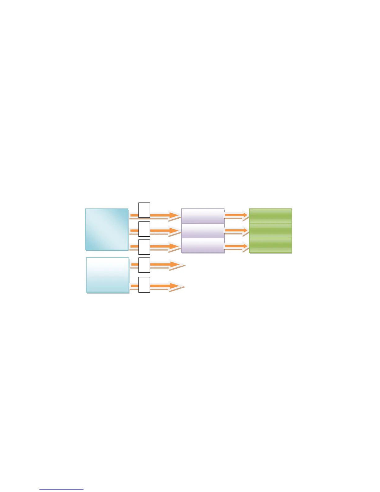
VGA signal output basic schemes:
① : PIN 10 output “R” signal ;
② : PIN 11 output “B” signal ;
③ : PIN 12 output “G” signal ;
④ : PIN 4 output “HS” signal ;
⑤ : PIN 2 output “VS” signal ;
VGA master chip : 74LV07 and 6303
Description:
6303
74LV07
75Ω(RG6)
75Ω(RG5)
 Loading...