10. PRECAUTIONS IN DISASSEMBLY AND REASSEMBLY
The [Bold] numbers in the descriptions below correspond to the item numbers in the Parts Lists and exploded
assembly diagram for the Model CJ 120V. And the numbers included in ( ) like as ([99]) means that of the Model
CJ 120VA.
10-1. Disassembly
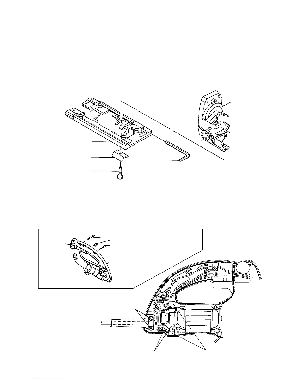
(1) Disassembly of the Base [70] ([73]) (Fig. 3)
Remove the Hex. Socket Hd. Bolt M5 x 14 [72] ([75]) by attached Hex Bar Wrench 4 mm [73] ([76]). Then
the Base [70] ([73]) and the Base Locker [71] ([74]) can be removed from the Gear Cover [45] ([48]).
Fig. 5
[45] ([48])
[73]
([76])
([73]) [70]
Brush Holder [23]
Tapping Screw (W/Flange)
D4 x 16 [15]
([74]) [71]
([75]) [72]
Fig. 3
Carbon Brush [22]
(2) Disassembly of Housing (A). (B) Set [1]
••••••••
for the Model CJ 120V (Figs. 4 and 5)
Remove the Seal Lock Screw (W/Washer) M4 x 10 [18], Tapping Screws (W/Flange) [4] [5], and open one
side of the housing. (Fig. 4) Then remove two Tapping Screws (W/Flange) D4 x 16 [15], Brush Holder [23]
with Carbon Brush [22], so the other side of the housing can also be separated from other assemblies.
(Fig. 5)
Hex. Bar Wrench 4 mm
Gear Cover
Base
Base Locker
Hex. Socket Hd. Bolt M5 x 14
Fig. 4
Housing
(A).(B) Set [1]
[4] Tapping Screw (W/Flange) D4 x 30
[18] Seak Lock Screw (W/Washer) M4 x 10
[5] Tapping Screw (W/Flange) D4 x 20
 Loading...