(Brass color)
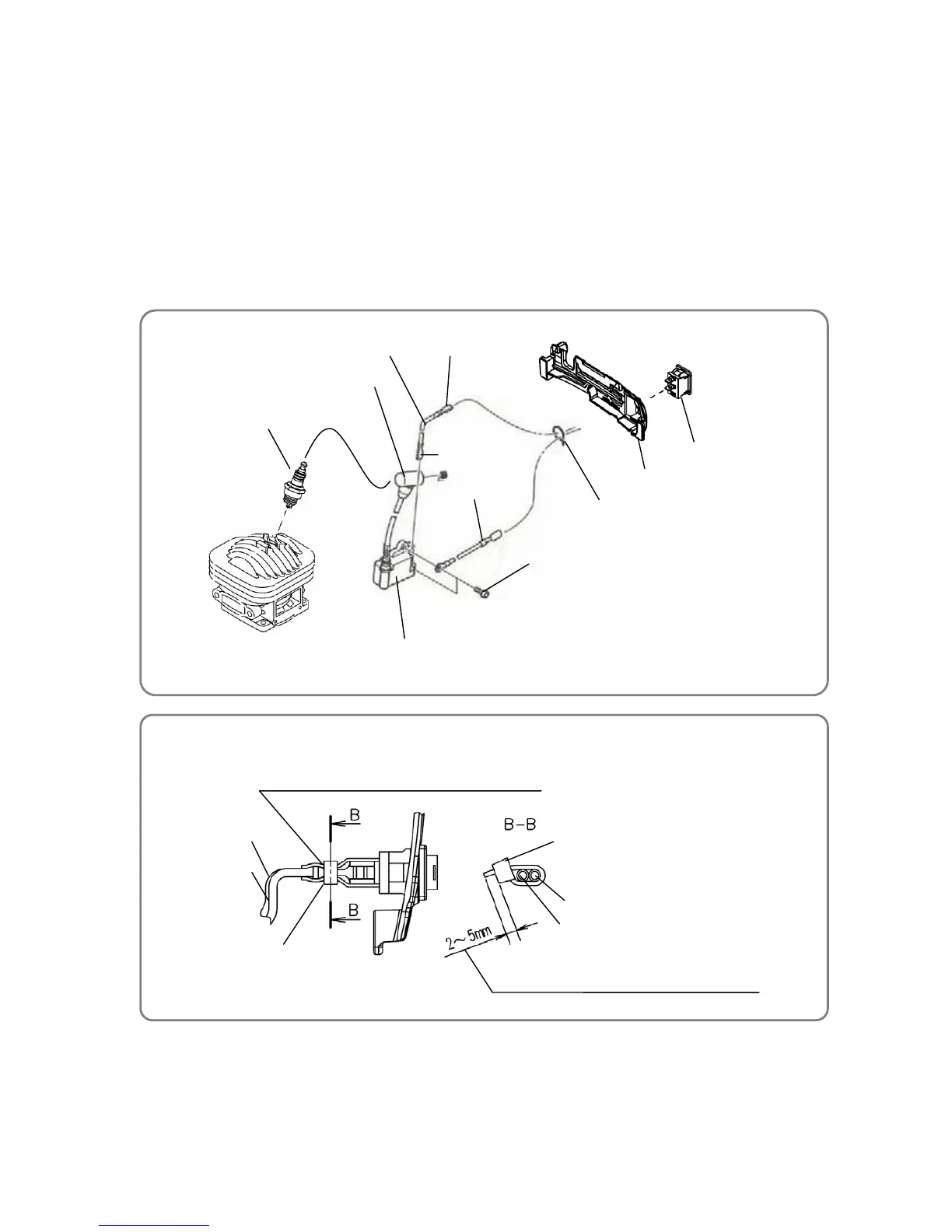
• Cable tie securing position
Cord (B) [164]
Cord (A)[163]
Cut off the surplus end of the Cable Tie [161] with
2 to 5 mm of strap projecting from its locking head.
Cable Tie [161]
Concave portion of Cord (A) [163] and Cord (B) [164]
Cord (B) [164]
Cord (A)[163]
Cable Tie [161]
8. Wiring diagram
The following diagram shows the wiring.
(1) Connect the connector (silver) of Cord (A) [163] to the Ignition Coil [166].
(2) Fix Cord (B) [164] to the Ignition Coil [166] with the Hex. Socket Hd. Bolt (W/Flange) M4 x 18 [167].
(3) Fit the Stop Switch [95] into the Operation Plate [94] so that indication “1” faces up.
(4) Connect the connectors (brass color) of Cord (A) [163] and Cord (B) [164] to the connectors of the Stop
Switch [95].
(5) Bundle together Cord (A) [163] and Cord (B) [164], and then secure the concave portion of the bundle
with the Cable Tie [161].
CAUTION: Do not get Cord (A) [163] and Cord (B) [164] caught in other parts.
 Loading...