-7-
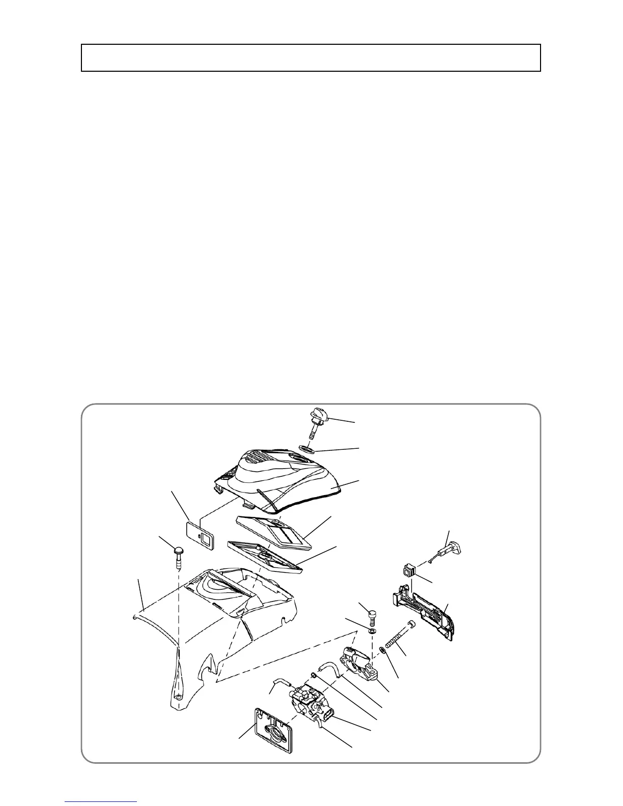
Cleaner Knob [6]
Knob Packing [7]
Cleaner Cover [2]
Cleaner Element (B) [8]
Cleaner Element (A) [9]
Cover Set Bolt [4]
Carburetor Insulator (C51) [50]
Carburetor Ass’y [52]
Cleaner Support [71]
Hex. Socket Hd. Bolt
M5 x 12 (Precote) [38]
Cylinder Cover [5]
Clip [31]
Fuel Pipe [68]
Hex. Socket Hd. Bolt M5 x 45 [70]
Operation Plate [94]
Choke Rod Rubber [92]
Choke Button [93]
Fuel Pipe (FKM) [51]
Fuel Pipe [72]
Shutter Plate [3]
Washer 5 [69]
Washer 5 [69]
Ɣ Cleaner and carburetor
1. Disassembly and reassembly of the cleaner and carburetor
[Tools required]
Ɣ Phillips screwdriver
Ɣ Hex. bar wrench (4mm)
(1) Disassembly
Ɣ Loosen the Cleaner Knob [6] and remove the Cleaner Cover [2].
Ɣ
Use a Phillips screwdriver to loosen the three Cover Set Bolts
[4]
, and then remove the Cylinder Cover
[5]
.
Ɣ Pull out Cleaner Element (A) [9] and Cleaner Element (B) [8].
Ɣ Remove the Clip [31] and pull out the Fuel Pipes [68] [51] [72] from the Carburetor Ass’y [52]. Use a
hex. bar wrench (4 mm) to remove the Hex. Socket Hd. Bolt M5 x 12 (Precote) [38] and two Hex.
Socket Hd. Bolts M5 x 45 [70]. Then remove the Cleaner Support [71] and Carburetor Ass’y [52].
(2) Reassembly
Reassembly can be conducted by reversing the disassembly procedure. However, special attention
should be given to the following items.
Ɣ Do not bend the Fuel Pipes [68][51][72]. (See “2. Connecting the fuel pipes” for details.)
Ɣ Apply 0.1 to 0.2 gram of Alvania Grease RL3 to the sliding portion of the Choke Rod Rubber [92] for
the Choke Button [93]. Pull out the Choke Button [93] and then turn the throttle of the carburetor.
Make sure that the Choke Button [93] returns automatically and the carburetor’s choke valve opens to
its initial position.
Ɣ Apply 0.1 to 0.2 gram of Alvania Grease RL3 to the lug portions (to be fitted in the grooves of the
Engine Case (A) Ass’y [87] and Engine Case (B) Ass’y [80])) of the Operation Plate [94].
Ɣ Be careful not to get Cord (A) [163] and Cord (B) [164] caught in the Cylinder Cover [5].
Disassembly and reassembly
 Loading...