--- 34 ---
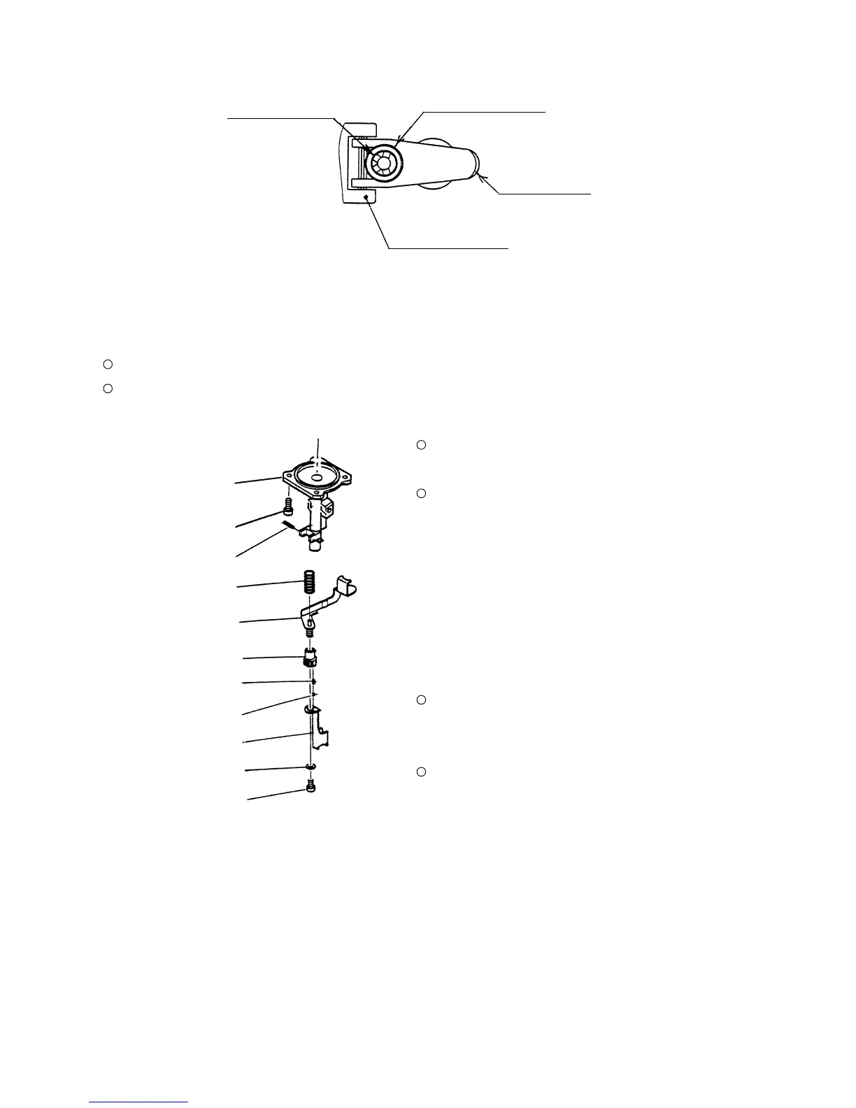
(a) Disassembly (See Fig. 18.)
Remove the Nose [32] and the pushing lever ass'y
from the main body according to 10-2-(3) (Fig. 14).
Pull out the Roll Pin D3 x 18 [34] and remove the
Hex. Socket Hd. Bolt M6 x 12 [53] to remove Pushing
Lever (A) [51], Pushing Lever (B) [47], Adjuster [48]
and other parts.
(b) Reassembly
Reassembly can be accomplished by following the
disassembly procedures in reverse. However, special
attention should be given to the following items.
The two Adjuster Springs [49] and the Steel Ball
D3.175 [50] are very small and apt to be lost.
Be careful when handling them.
After reassembly, check that the Adjuster [48] turns
smoothly by hand.
10-4. Disassembly and Reassembly of the Driving Section
Tools required
Hexagonal bar wrench (5 mm and 6 mm)
Roll pin puller (3 mm (0.118") dia.)
Fig. 18
Pushing Lever (A) [51]
Washer [52]
Nose [32]
Nylock Hex. Socket
Hd. Bolt M8 x 22 [33]
Spring [46]
Hex. Socket Hd. Bolt
M6 x 12 [53]
Pushing Lever (B) [47]
Fig. 17
2.5 mm dia. hole
Body Ass'y [25]
Trigger [59]
Valve Bushing [57]
Roll Pin D3 x 18 [34]
Adjuster [48]
Adjuster Spring [49]
Steel Ball D3.175 [50]
 Loading...