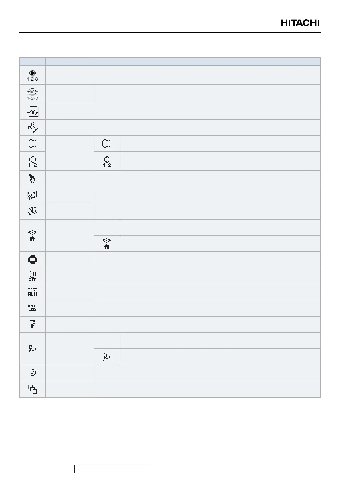
7.2.2 Icons for the comprehensive view
Icon Name Explanation
Pump
This icon informs about pump operation.
There are three available pumps on the system. Each one is numbered, and its corresponding number is
displayed below to the pump icon when it is operating
Heater step Indicates which of the 3 possible heater steps is applied on space heating
DHW Heater Informs about DHW Heater operation. (If it is enabled)
Solar Combination with solar energy
Compressor
Compressor enabled (For YUTAKI S, S COMBI and M)
Compressors enabled.
1: R410A/R32
2: R-134a (For YUTAKI S80)
Boiler Auxiliary boiler is working
Tariff Tariff signal informs about some cost conditions of the consumption of the system
Defrost Defrost function is active
Central/Local
- No icon means local mode
Central mode (Three types of control: Water, Air or Full)
Forced OFF
When forced off Input is congured and its signal is received, all the congured items on the comprehensive
view (C1, C2, DHW, and/or SWP) are shown in OFF, with this small icon below
Auto ON/OFF
When daily average is over auto summer switch-off temperature, circuits 1 and 2 are forced to OFF (Only if
Auto ON/OFF enabled)
Test Run Informs about the activation of the “Test Run” function
Anti-Legionella Activation of the Anti-Legionella operation
DHW boost It activates the DHW heater for an immediate DHW operation
ECO mode
- No icon means Comfort mode
ECO/Comfort mode for circuits 1 and 2
Night Shift Informs about night shift operation
CASCADE
CONTROLLER
Informs about the activation of the “CASCADE” mode.
UNIT CONTROLLER
PMML0510 rev.1 - 10/2019
68
 Loading...