The manometer is placed at different positions according to each unit model
YUTAKI S / S COMBI
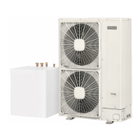
In YUTAKI S and S COMBI models, the manometer is installed factory supplied as it is shown:
YUTAKI S YUTAKI S COMBI
Manometer
Manometer
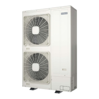
YUTAKI M
For the YUTAKI M series it is highly recommended to install, eld supplied, a manometer gauge attached to the water inlet pipe and
after the shut-off valve.
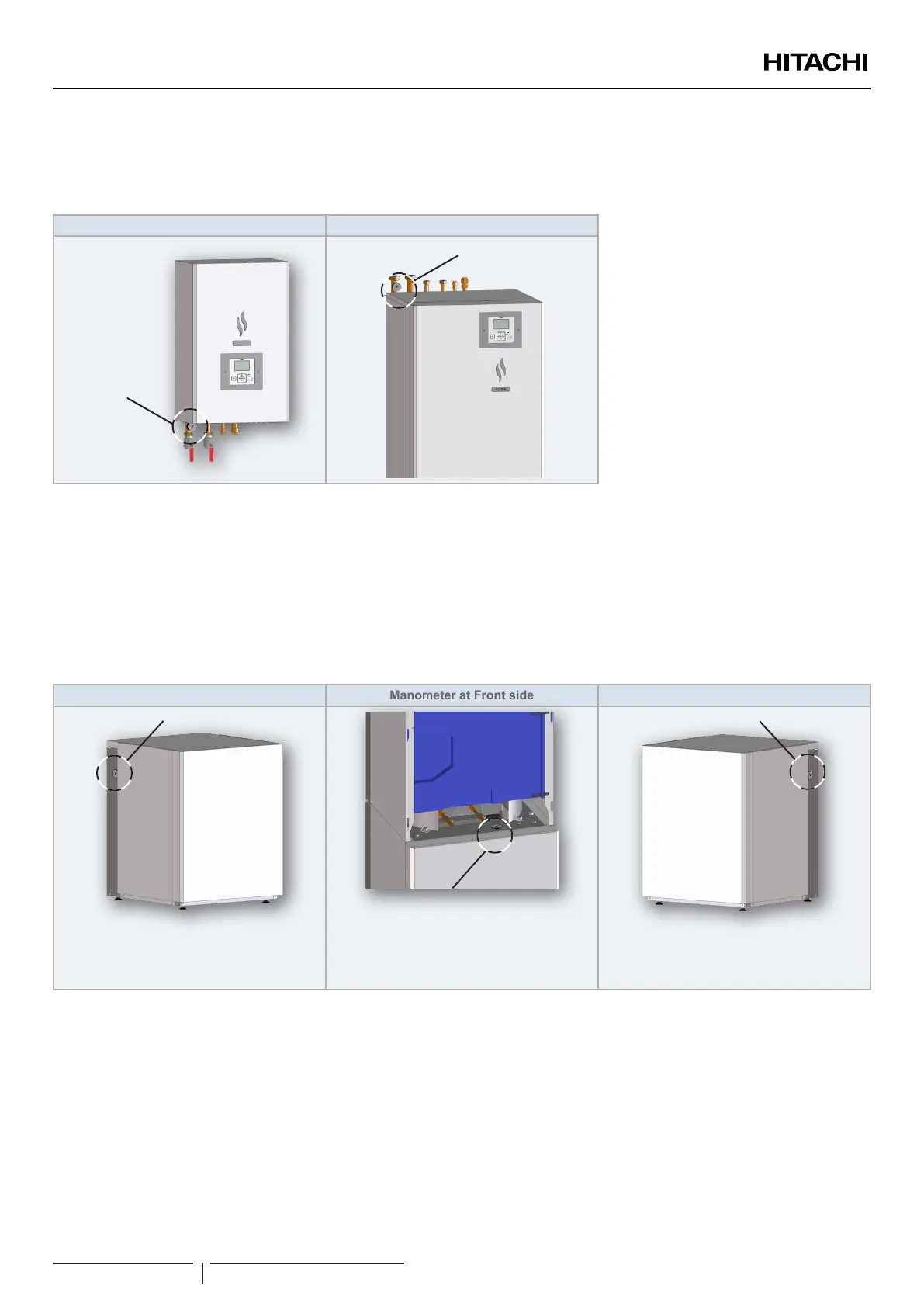
YUTAKI S80 Type 2
YUTAKI S 80 has special congurations for the position of the manometer. While it is factory supplied in only one position (left side),
it can be moved by the installer to the right side or to the front of the unit. For example, in case of a wall at the left side or at both
sides of the YUTAKI S80 unit, respectively.
Manometer at Left side (factory supplied) Manometer at Front side Manometer at Right side
Manometer
? NOTE
This is the factory supplied location of the
manometer
Manometer
? NOTE
This conguration requires removing the front
panel, both for mounting and to display the
gauge.
Manometer
? NOTE
Installer can change the location of the manometer
gauge
? NOTE
The water pressure must remain above 1 bar in order to prevent air from entering the circuit, and below 3.0 bars (safety valve opening value).
- DHW (if used): Check there is no loss of pressure and ensure that DHW pressure is not higher than 6 bars. Connect a
gauge to the DHW drain port for this purpose.
10 Security water valve for DHW (if used):
• Operation: Check the correct operation of the security water valve (pressure and temperature relief valve) at the DHW inlet
connection. Remember that this element must ensure that the following functions are pro vided: Pressure protection, non-
return function, shut-off valve, lling and draining.
MAINTENANCE
PMML0510 rev.1 - 10/2019
152
 Loading...