? NOTE
• The indoor unit is equipped with an automatic air purger (factory
supplied) at the highest location of the indoor unit. Anyway, if there
are higher points in the water installation, air might be trapped inside
water pipes, which could cause system malfunction. In that case,
additional air purgers (eld supplied) should be installed to ensure
no air enters into the water circuit. The air vents should be located at
points which are easily accessible for servicing.
• The water pressure indicated on the indoor unit manometer may vary
depending on the water temperature (the higher temperature, the
higher pressure). Nevertheless, it must remain above 1 bar in order
to prevent air from entering the circuit.
• Fill in the circuit with tap water. The water in the heating installation
must comply with EN directive 98/83 EC. Non-sanitary controlled
water is not recommended (for example, water from wells, rivers,
lakes, etc.)
• The maximum water pressure is 3 bar (nominal opening pressure of
the safety valve). Provide adequate reduction pressure device in the
water circuit to ensure that the maximum pressure is NOT exceeded.
• For heating oor system, air should be purged by means of an external
pump and an open circuit to prevent the formation of air pockets.
• Check carefully for leaks in the water circuit, connections and circuit
elements.
5 ELECTRICAL AND CONTROL
SETTINGS
5.1 GENERAL CHECK
• Make sure that the following conditions related to power
supply installation are satised:
- The power capacity of the electrical installation is large
enough to support the power demand of the YUTAKI
system (outdoor unit + indoor unit + DHW tank (if apply)).
- The power supply voltage is within ±10% of the rated
voltage.
- The impedance of the power supply line is low enough
to avoid any voltage drop of more than 15% of the rated
voltage.
• Following the Council Directive 2014/30/EU, relating to
electromagnetic compatibility, the table below indicates the
Maximum permitted system impedance Z
max
at the interface
point of the user’s supply, in accordance with EN61000-3-11.
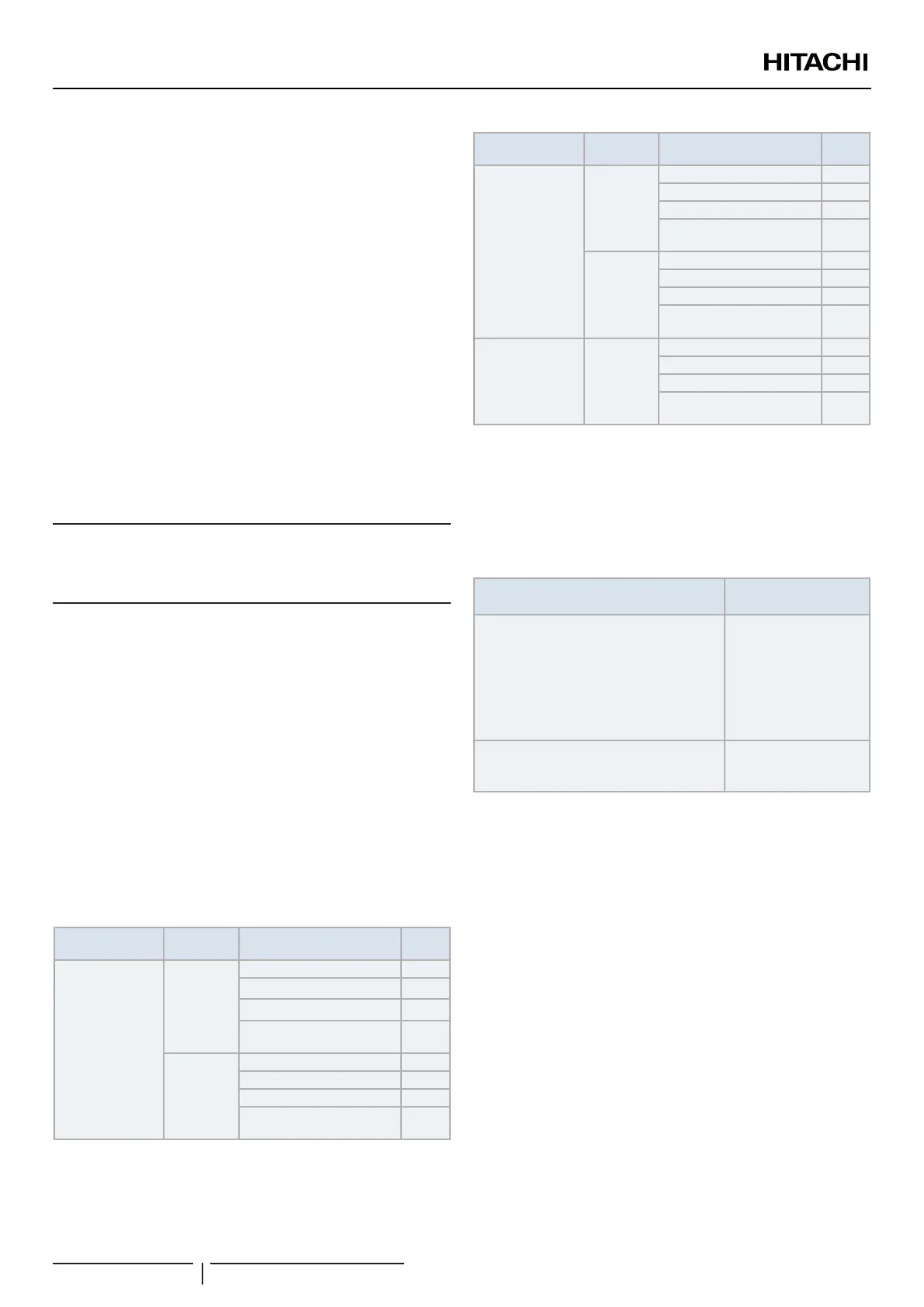
Model
Power
supply
Operation mode
Z
max
(Ω) (*)
RWM-(2.0-3.0)R1E
1~ 230V
50Hz
Without electric heaters -
With electric heater -
With DHW tank heater -
With electric and DHW tank
heaters
0.28
3N~ 400V
50Hz
Without electric heaters -
With electric heater -
With DHW tank heater -
With electric and DHW tank
heaters
-
Model
Power
supply
Operation mode
Z
max
(Ω) (*)
RWM-(4.0-6.0)N1E
1~ 230V
50Hz
Without electric heaters -
With electric heater 0.28
With DHW tank heater -
With electric and DHW tank
heaters
0.19
3N~ 400V
50Hz
Without electric heaters -
With electric heater -
With DHW tank heater -
With electric and DHW tank
heaters
-
RWM-(8.0/10.0)N1E
3N~ 400V
50Hz
Without electric heaters -
With electric heater -
With DHW tank heater -
With electric and DHW tank
heaters
-
? NOTE
The data corresponding to DHW tank heater is calculated in combination
with the domestic hot water tank accessory “DHWT-(200/300)S-3.0H2E”.
• The status of Harmonics for each model, regarding compliance
with EN 61000-3-2 and EN 61000-3-12, is as follows:
Status regarding compliance with
EN 61000-3-2 and EN 61000-3-12
Models
Equipment complying with EN 61000-3-2
RWM-2.0R1E
RWM-2.5R1E
RWM-3.0R1E
RWM-4.0N1E (3N~)
RWM-5.0N1E (3N~)
RWM-6.0N1E (3N~)
RWM-8.0N1E
RWM-10.0N1E
Equipment complying with EN 61000-3-12
RWM-4.0N1E (1~)
RWM-5.0N1E (1~)
RWM-6.0N1E (1~)
• Check to ensure that existing installation (mains power
switches, circuit breakers, wires, connectors and wire
terminals) already complies with the national and local
regulations.
• The use of the DHW tank heater is disabled as setting. If it
is desired to enable the DHW tank heater operation during
normal indoor unit operation, adjust the DSW4 pin 3 of the
PCB1 to the ON position and use the adequate protections.
Refer to the section “5.6 Setting of DIP switches and RSW
switches” for the detailed information.
Electrical and control settings
PMML0574 rev.1 - 09/2021
12
 Loading...