6 UNIT INSTALLATION
6.1 GENERAL NOTES
6.1.1 Selection of the installation location
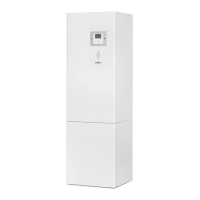
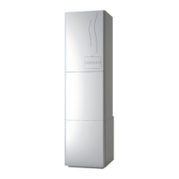
The indoor unit of the split system with air to water heat pump
must be installed following these basic requirements:
• The indoor unit is intended to be installed in an indoor place
and for ambient temperatures ranging 5~30°C. The ambient
temperature around the indoor unit must be >5°C to prevent
water from freezing.
• The unit is prepared to be wall mounted (wall bracket is
factory supplied), so make sure that selected wall is at and
is made of a non-combustible surface, strong enough for
supporting the indoor unit weight.
• Be sure to maintain the recommended servicing space for
future unit servicing and guarantee enough air circulation
around the unit (See “3.1 Service space” section).
• Take into account that two shut-o valves (factory supplied)
must be installed at the indoor unit inlet/outlet connections.
• Keep water draining provisions. The safety valve and the air
purge are provided with a drain pipe which are located at the
bottom side of the unit.
• If the event of installing the “Cooling kit” accessory, the
installer is responsible for proper installation and draining.
• Protect the indoor unit against the entry of small animals
(like rats) which could making contact with the wires, the
drain pipe, electrical parts and may damage unprotected
parts, and at the worst, a re will occur.
• Install it in a no-frost environment.
• Do not install the indoor unit in a location with very high
humidity.
• Do not install the indoor unit where electromagnetic waves
are directly radiated to the electrical box.
• Install the unit in a place where in case of water leakage,
any damage to the installation space cannot be produced.
• Install noise lter when the power supply emits harmful
noises.
• To avoid re or explosion, do not install the unit in a
ammable environment.
• The air to water heat pump must be installed by a service
technician. The installation must comply with local and
European regulations.
• Try to avoid to put any objects or tools above the indoor unit.
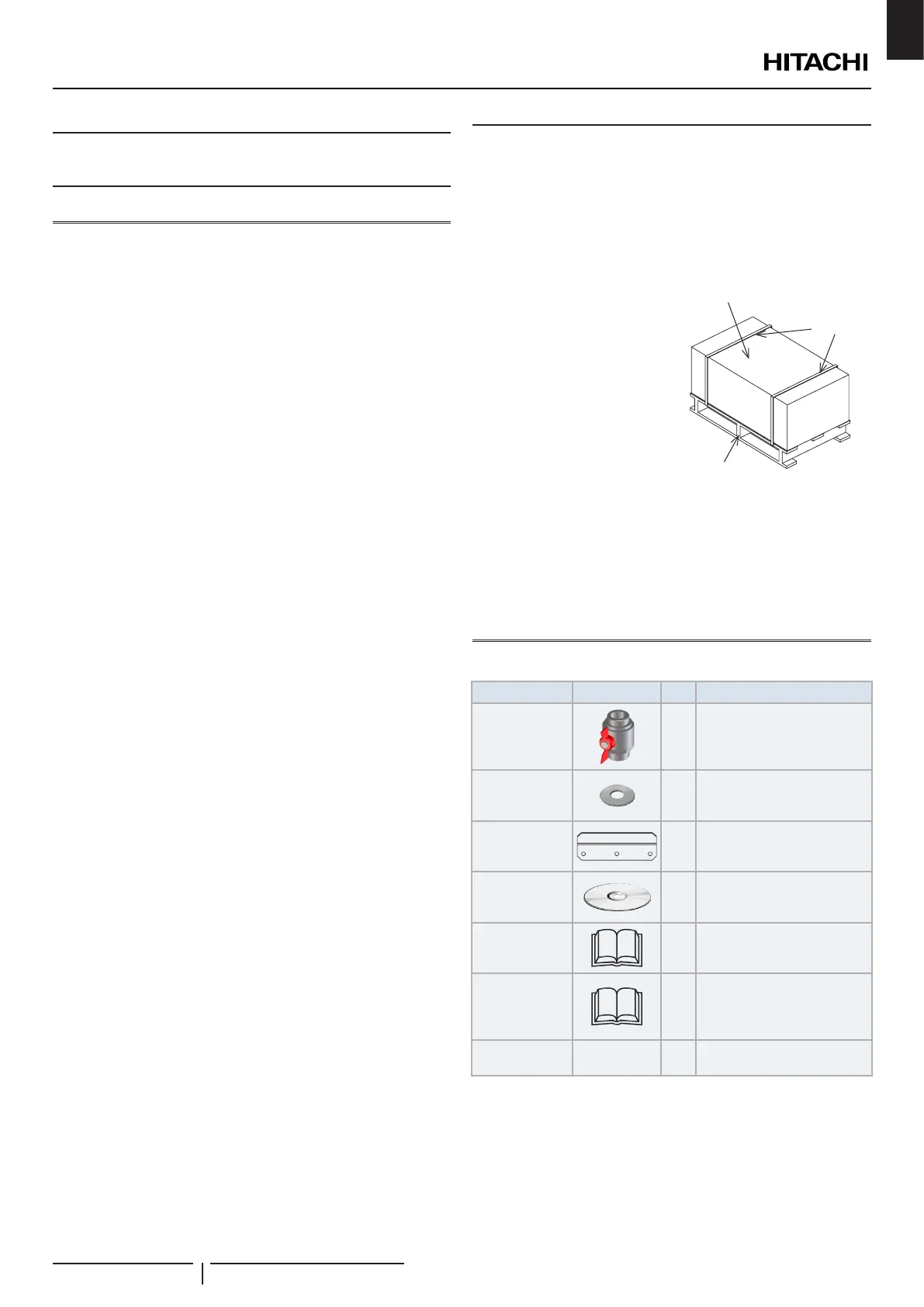
6.1.2 Unpacking
All units are supplied with a wooden base, packed by a
cardboard box and plastic bag.
Firstly to unpack it, place the unit on the assembly area as close
as possible to its nal installation location, to avoid damages in
transport. Two persons are required.
1 Cut the strapping bands and
remove the adhesive tapes.
2 Remove the carton assembly
and then the plastic bag
around the unit.
3 Unscrew the 4 screws which
x the unit to the wooden
base.
4 Remove the indoor unit from
the wooden base and place
it carefully on the oor, as
near as possible to its nal
location.
Wooden
base
Strapping
bands
Carton
assembly
! CAUTION
• Be careful with the Installation and Operation manual and with the
factory-supplied accessories box located besides the unit.
• Two people are required when lifting because of the weight of the
unit.
6.1.3 Factory-supplied indoor unit components
Accessory Image Qty. Purpose
Shut-o valve
(2-3HP: 1”)
(4-10HP: 1-1/4”)
2
To make easier the installation
work in the space heating
water inlet/outlet connections.
For a better servicing.
Gasket 4
Two gaskets for each space
heating connections
(inlet/outlet)
Wall support 1
For hanging the unit on the
wall
CD-ROM 1
With the detailed Installation
and operation manual
Instruction
manual
1
Basic instructions for the
installation of the device.
Instruction
manual
1
Additional safety manual for
R32 refrigerant air conditioner
and heat pump according to
IEC 60335-2-40:2018
Declaration of
conformity
- 1 -
? NOTE
• The previous accessories are supplied inside the packing assembly
(besides the indoor unit).
• Additional refrigerant piping (eld supplied) for connections to outdoor
unit needs to be available.
• If some of these accessories are not packed with the unit or any
damage to the unit is detected, please contact your dealer.
UNIT INSTALLATION
PMML0574 rev.1 - 09/2021
21
EN
 Loading...