11. OPERATION
1. INVERTER TYPE GENERATOR
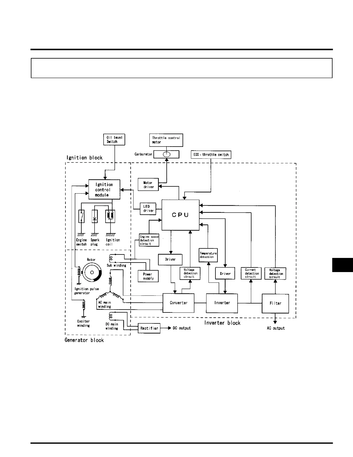
CONSTRUCTION
The Inverter generator has an outer and an inner rotating set of magnets for both the generator and the ignition. The
inner set of magnets generate AC in the stator windings, while the outer set generates AC for the ignition coil. A multi-
pole coil is used on the stator (15 poles for the AC winding, 6 poles for the DC winding, 1 pole for the sub winding, and
1 pole for the exciter winding). The AC coil in the stator is picked up by the inverter.
Operating Principles
When the rotor rotates, the AC (3-phase) is generated at the AC main winding, which is converted into DC by the
regulator/rectifier. The voltage is stabilized by the regulator/rectifier in the converter simultaneously. The AC generated
at the sub winding becomes the power source for each circuit and elemental device, such as an inverter built-in power
transistor. Getting a signal from the oscillator circuit, the inverter that controls the LED generates the AC (single phase)
of the proper frequency.
• AC Overload Protection System
The power output indicator light (green LED) is on while the generator is running with normal load. When overloaded,
the overload warning light turns on by getting signal from the output current detecting circuit to indicate overloading.
When the generator runs overloaded for more than 5 seconds, the circuit cuts off the AC to protect the generator. When
the output is cut off due to overloading, stop the engine and disconnect the attached electrical device from the
generator to remove the load. Start the engine again. The LED (green) should turn on.
1. INVERTER TYPE GENERATOR......... 11-1
2. FULL TRANSISTOR IGNITION .......... 11-2
3. ECO-THROTTLE
(ELECTRICAL GOVERNOR) ..............11-3
 Loading...