4
Terminal designations
Conventional Systems Heat pump systems
Terminal Description Terminal Description
S/S
Input for a wired indoor,
outdoor sensor
S/S
Input for a wired indoor,
outdoor sensor
Y Compressor Stage 1 Y Compressor Stage 1
Y2 Compressor Stage 2 Y2 Compressor Stage 2
G Fan Relay G Fan Relay
C
24VAC Common wire from
secondary side of cooling
transformer (if 2 transformers)
C
24VAC Common wire from
secondary side of cooling
transformer
K*
Connect to K on C-wire
adaptor
K*
Connect to K on C-wire
adaptor
U/U** Relay for ventilation U/U** Relay for ventilation
A L/A
Connect to compressor
monitor
W Heat Stage 1 O/B
Changeover valve for heat
pumps
W2 Heat Stage 2 Aux Backup Heat
E Emergency Heat
R 24 VAC Heating transformer R 24 VAC Heating transformer
Rc 24 VAC Cooling transformer Rc 24 VAC Cooling transformer
* The THP9045A1098 C-wire adaptor is used on heat/cool systems when you only have four wires at
the thermostat and you need a fifth wire for a common wire. Use the K terminal in place of the Y and
G terminals on conventional or heat pump systems to provide control of the fan and the compressor
through a single wire—the unused wire then becomes your common wire. See THP9045 instructions
for more information.
** Ventilation is not available on all models. When the U slider is in the down position (2 wires), the U
contacts are a dry set of contacts. If your ventilation system requires 24 volts, move the U slider to the
up position (1 wire). Lower U terminal is internally jumped to the Rc terminal. In this application, you
would hook up one wire from your damper to the upper U terminal and the other to the common side of
the transformer.
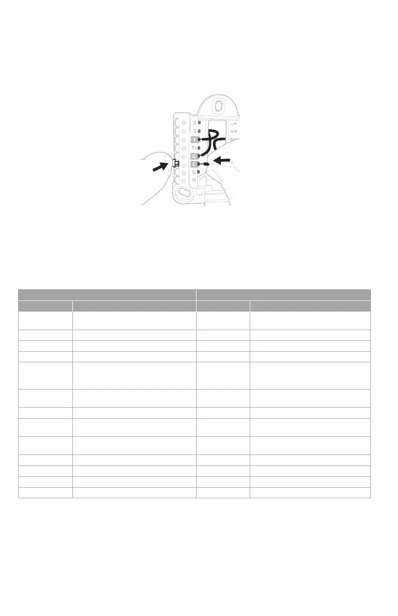
Wiring UWP
Push down on the tabs to put the wires into the inner holes of their corresponding termi nals
on the UWP (one wire per terminal) until they are firmly in place. Gently tug on the wires to
verify they are secure. If you need to release the wires again, push down the terminal tabs
on the sides of the UWP.
This wiring is just an example,
yours may vary.
 Loading...