511391 201T User Manual 23
2/07 Honeywell
USER INTERFACE
Testing Procedure
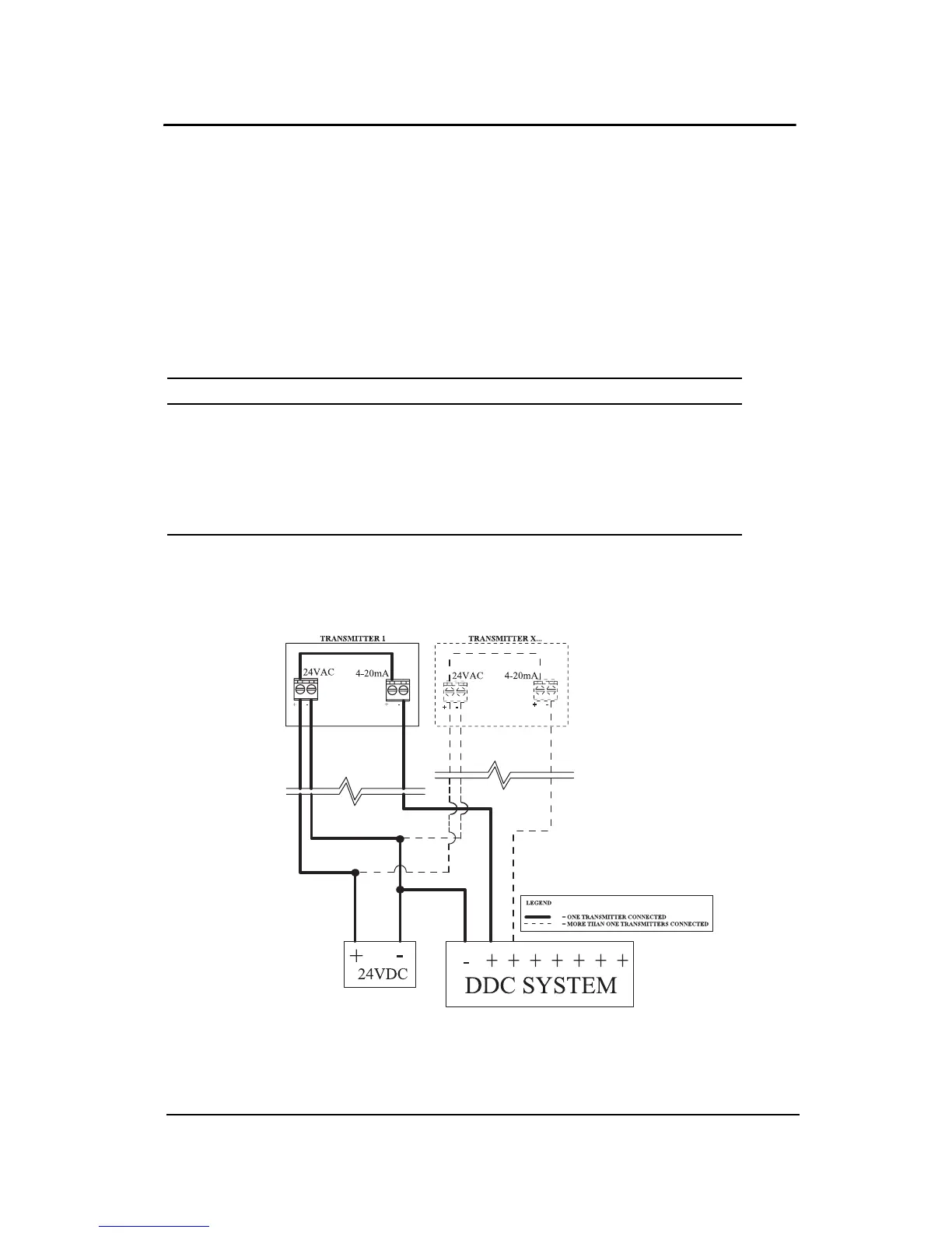
4-20 mA OUTPUT LOOP-POWERED OPERATION (Factory Setting)
The 4-20 mA output is factory set for loop-powered operation and
requires a power source of 12 Vdc to 30 Vdc. The overall impedance
depends on the voltage supplied at the 4-20 mA loop. Set jumpers on
S3 at 2-3, 4-5 and 6-7 for this type of configuration (pin 1 being next to
S3).
3-wire configuration
Permitted impedance in the 4@20 mA loop
Voltage Source Applied Total Impedance
12 Vdc 400 Ohms
16 Vdc 600 Ohms
20 Vdc 800 Ohms
24 Vdc 1 000 Ohms
30 Vdc 1 300 Ohms
 Loading...