EasyManuals Logo
Home>Honeywell>Gas Detectors>201T

Honeywell 201T User Manual

Honeywell 201T
66 pages
To Next Page IconTo Next Page
To Previous Page IconTo Previous Page
Page #24 background imageLoading...
Page #24 background image
22 201T User Manual 511391
Honeywell 2/07
USER INTERFACE
Testing Procedure
4-20 mA CONFIGURATION
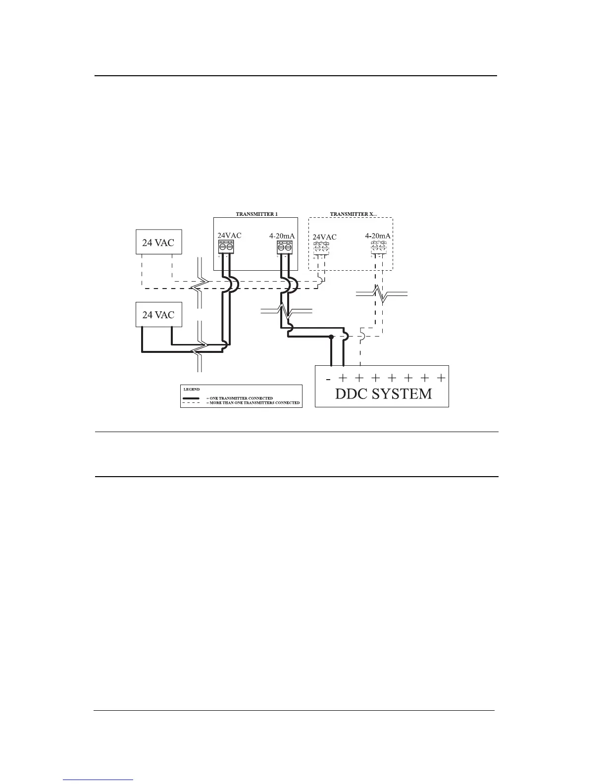
4-20 mA CURRENT SOURCING OUTPUT CONFIGURATION
The transmitter supplies the loop current. The maximum impedance
supported by the loop is 400 ohms. Set jumpers on S3 at 1-2, 3-4 and
5-6 (pin 1 being next to S3).
WARNING
A dedicated power supply must be used with each unit.
Considerable damage may occur if this condition is not strictly
followed.

Questions and Answers:

Question and Answer IconNeed help?

Do you have a question about the Honeywell 201T and is the answer not in the manual?

Honeywell 201T Specifications

General IconGeneral
BrandHoneywell
Model201T
CategoryGas Detectors
LanguageEnglish

Related product manuals