K3590-ADV4 2/09 Rev. A
ADEMCO 6150 & 6160
REMOTE KEYPADS
INSTALLATION AND SETUP GUIDE
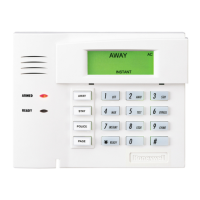
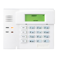
Keypad Features
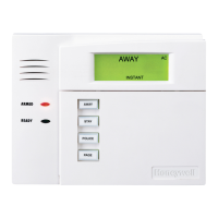
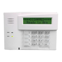
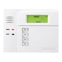
ADEMCO 6150
Fixed-Word
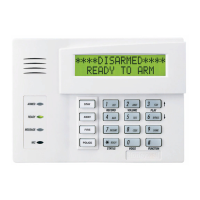
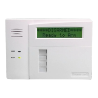
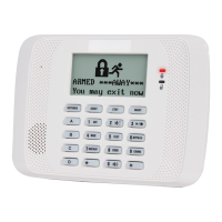
ADEMCO 6160
2-Line Alpha
Backlit Display
9(see note) 9 (see note)
Dedicated Function Keys
9 9
Built-in Sounder Piezo Speaker
Note: Permanent display backlighting is an option on some controls (see the control's instructions for details).
GENERAL INFORMATION
The ADEMCO 6150 and ADEMCO 6160 are addressable
Remote Keypads designed for use with ADEMCO control
panels. Addresses are set via the keypad keys.
The keys on the keypads are continuously backlit for
convenience.
Supervised by control panel (if supported).
KEYPAD DISPLAYS AND LEDS
The keypads have the following display features:
Model
Fixed
Word
Display
2-line
Alpha
Display
2-digit
Zone
Identifier
Custom
Zone
Descriptors
6150 X X
6160 X X
The following table shows the LEDs and their functions:
LED Function
Red Lights when the system is armed in any mode
Green Lights when the system is "ready" to be armed.
SPECIAL FUNCTION KEYS
The keypads also feature function keys. These keys may be
programmed for panic alarms or other special functions
such as macros. See the control's instructions for details.
Function keys must be held down for at least 2
seconds to activate an alarm; key pairs are activated
immediately.
Function Keys
A or [1] and [✻]
B or [✻] and [#]
C or [3] and [#]
D
WIRING AND INSTALLATION
The keypads can be surface mounted directly to a drywall,
or to a single- or double-gang electrical box.
1. Push the two case release snaps at the bottom of the
keypad with the blade of a medium screwdriver (this will
push in the release snap), then pull that side of the case
back away. Insert the screwdriver in the side of the
keypad (between the front and back case) and gently
twist to release the side locking tab. Repeat for the other
side. Refer to Figure 1 for location of the case back
release snaps and locking tabs.
2. Route wiring from the control panel through the opening
in the case back.
3. Mount the case back to a wall or electrical box.
4. Wire directly from the keypad’s terminal block to the
terminal block on the control panel. (See Wiring Table
below).
NOTE: No more than one wire per terminal may be
connected. If daisy-chained configuration is required,
pig-tail wires together so that only one wire is
terminated under the screw. Use 16-24 AWG wire only!
Wiring Table (All Keypads)
Keypad Control Panel Wire Color
SG
Data In Green
– – Aux Pwr (GND) Black
+ + Aux. Pwr Red
TY
Data Out Yellow
See the control panel’s Installation and Setup Guide for
more complete details.
5. Reattach the keypad to its case back.