SOLID STATE ECONOMIZER SYSTEM
63-2484—1
17
1
1
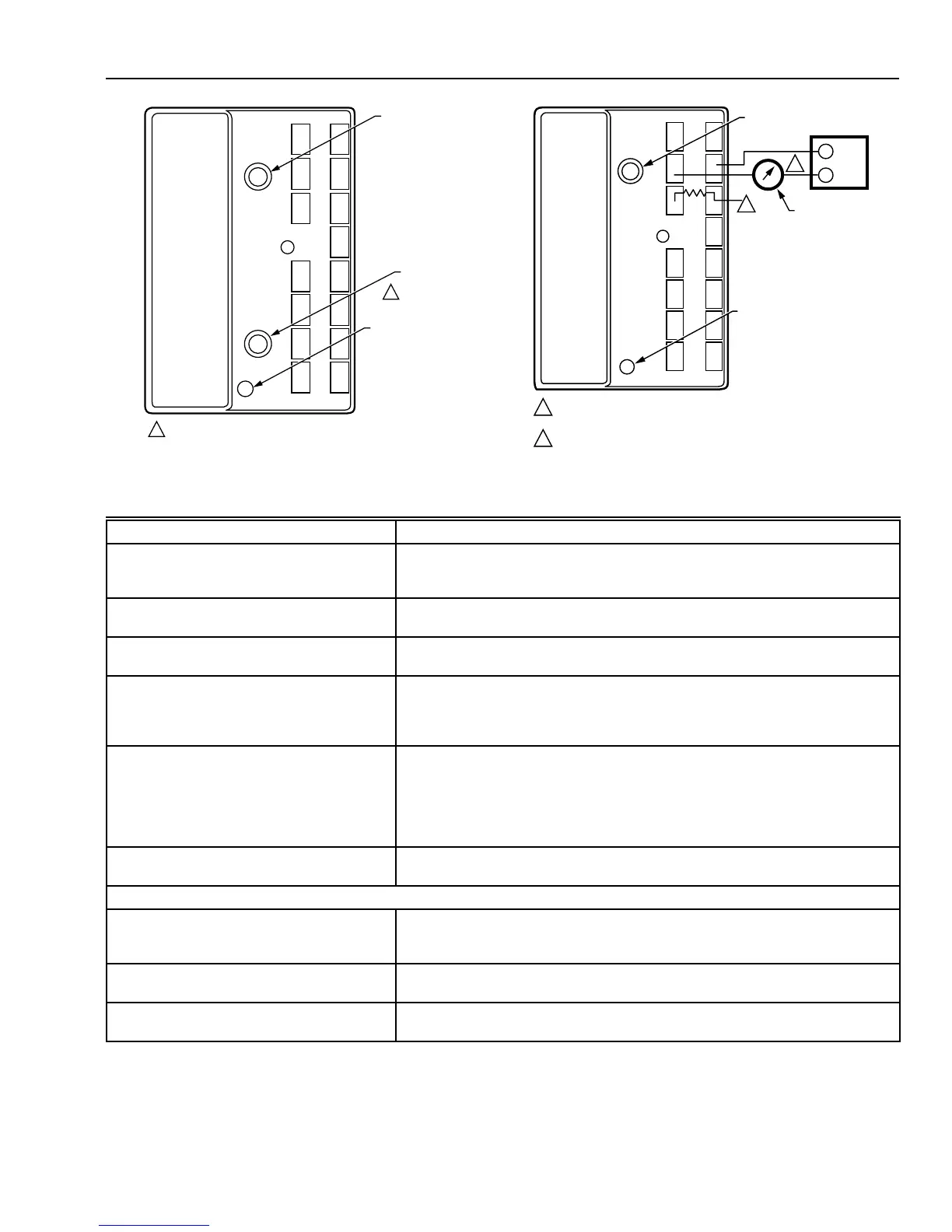
M9098B
ENTHALPY
CHANGEOVER
SETPOINT
MINIMUM
DAMPER
POSITION
SETTING
LED LIGHTS
WHEN OUTDOOR
AIR IS SUITABLE
FOR FREE COOLING
MINIMUM DAMPER POSITION ADJUSTMENT
IS PRESENT ONLY ON W7459A,D MODELS.
Fig. 20. Location of enthalpy setpoint potentiometer,
minimum position potentiometer and LED.
1
1
2
2
M9097
ENTHALPY CHANGEOVER
SETPOINT
LED LIGHTS WHEN
OUTDOOR AIR IS SUITABLE
FOR FREE COOLING
INSERT DC MILLIAMMETER BETWEEN S
O
AND S FOR CHECKOUT
AND TROUBLESHOOTING.
JUMPER USED FOR SINGLE ENTHALPY CONTROL.
TR
TR1
A
BC
D
S
O
S
R
+
+
+
C7400
620 OHM
JUMPER
DC
MILLIAMMETER
W7459
S
+
Fig. 21. Meter location for checkout and troubleshooting.
Table 6. Troubleshooting modulating economizer—outdoor enthalpy above setpoint.
NOTES:
1. Standard economizer position based on enthalpy control set on the A setting and 50 percent relative humidity.
2. Closed position is either the minimum position or fully closed, depending on the job setting.
3. Opening/closing is dependent on the mixed air temperature.
Condition on Logic Module Should Be Condition Not Met
1. Red LED not lighted. 1. If the LED glows, the Logic Module thinks it is in the Economizer mode.
Verify that conditions are above the enthalpy setpoint, see Note 2. Check
wiring to Enthalpy Control for a short from {SO} and {+}.
2. 24 Vac to terminals {TR} and {TR1}. 2. Check the wiring from [G] and [C] on the unit low voltage terminal strip.
{TR} and {TR1} power the actuator.
3. 24 Vac to terminals {1} and {TR1}. 3. Verify that there is a call for cooling from the thermostat. Without a call for
cooling, the compressor can not be in the normal air conditioning mode.
4. 24 Vac to terminals {2} and {TR1}. 4. If 24 Vac is not on {2} and {TR1}, the internal switch is not set correctly.
Remove the {SO} wire from the module. If 24 Vac is on {2} and {TR1}, the
enthalpy control is bad or the {SO} and {+} wires are shorted together. If no
voltage to {2} and {TR1}, the module is bad.
5. Continuity on terminals {1} and {2}, {3}
and {4}.
5. If there is not continuity for terminals {1} and {2}, the internal switch is not
in the correct position and either the module or the enthalpy control is
defective. If there is continuity from terminals {1} and {2}, the red LED
should not be lighted. If there is continuity on terminals {3} and {5}, the
internal switch is correctly energized. The damper actuator should be in a
modulating mode.
6. Compressor does not operate with all
above conditions correct.
6. Check the wiring from {2} to Y1 on the unit low voltage control board.
Verify that 24 Vac is not on Y1 and C.
Second Stage
7. 24 Vac to terminals {3} and {TR1}. 7. Verify that you have a two-stage thermostat. Check for a call for a second
stage cooling. If 24 Vac is not on {3} and {TR1}, check wiring from Y2 on
the thermostat to the module.
8. 24 Vac to terminals {4} and {TR1}. 8. If {4} and {TR1} do not have 24 Vac, and {3} and {TR1} have 24 Vac, the
internal switch is not in the correct position. The module is defective.
9. Compressor does not operate with
second stage conditions met.
9. If all other functions are correct, check wiring from {4} to Y2 on the unit low
voltage terminal board.
{ } Terminals on the logic module.
[ ] Low voltage input from unit or thermostat.
 Loading...


