SOLID STATE ECONOMIZER SYSTEM
63-2484—1
6
Table 3. W7459A,C,D Specifications.
Model
For Use with
Actuator
Discharge Air
Temperature Input
Minimum Position
Potentiometer Adjustment
Terminals for Remote
Minimum Damper Position
Output
Relays
W7459A M7415 Thermistor Sensor Yes Yes 2 spdt
W7459C M8405 Spst control No. Minimum position
adjustment is built into
M8405 Actuator
No 2 spdt
W7459D
a
M7415 Thermistor Sensor
C7150B or C7046A
Yes Yes 2 spdt
a
W7459D has a high enthalpy limit and defaults to mechanical cooling when the outdoor enthalpy reaches the preset limit.
Do not use a dry bulb sensor for a high temperature limit.
INSTALLATION
When Installing these Products…
1. Read these instructions carefully. Failure to follow them
could damage the product or cause a hazardous
condition.
2. Check the ratings given in the instructions and marked
on the product to make sure the product is suitable for
your application.
3. Installer must be a trained, experienced service
technician.
4. After installation is complete, check out the product
operation as provided in these instructions.
CAUTION
CAN CAUSE ELECTRICAL SHOCK OR
EQUIPMENT DAMAGE.
Disconnect power supply before connecting wiring.
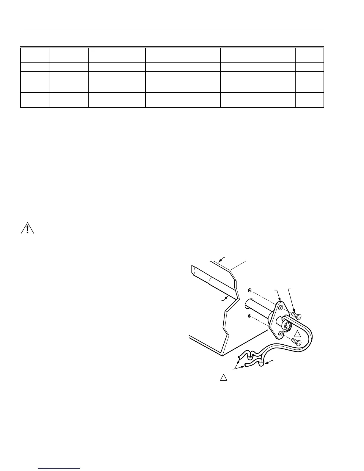
C7046C Discharge Air Temperature Sensor
The sensor assembly consists of an aluminum sensor
probe (element housed internally) with attached flange that
can be mounted on a flat duct or plenum surface, or in a
2 in. by 4 in. (51 by 102 mm) junction box, using two no. 8
screws. Connections to the sensor are made through two
6 in. (152 mm) leadwires.
Location
Locate the sensor in the air duct or plenum where it can
sample average air temperature. Avoid locations where air
stratification can cause sensing errors.
Mounting
To mount the C7046C Sensor on a flat duct or plenum
surface (see Fig. 7):
쐃 Cut a 1/2 in (13 mm) hole in the duct or plenum surface
at the desired location.
쐇 Insert the sensor probe into the duct or plenum hole
until the flange rests against the duct or plenum wall.
SCREWS NOT PROVIDED.1
SENSOR PROBE
SYSTEM DUCT OR PLENUM
FLANGE
NO. 8
MOUNTING
SCREWS (2)
TO APPROPRIATE
SYSTEM COMPONENTS
(SEE WIRING DIAGRAM)
SENSOR WIRES WITH
2 SOLDERLESS
CONNECTORS
1
M9086
Fig. 7. Mounting C7046C Air Temperature
Sensor on duct or plenum.
쐋 If necessary, use the flange as a template to mark and
drill two holes for no. 8 mounting screws.
쐏 Fasten the sensor to the duct or plenum surface with
the two no. 8 sheet metal screws (not provided).
To mount the C7046C Sensor in a junction box (see Fig. 8):
쐃 Cut a 1/2 in (13 mm) hole in the duct or plenum surface
at the desired location.
쐇 Remove the center rear knockout from the junction box
and insert the sensor probe through the knockout with
the flange flat against the junction box.
쐋 Using the flange as a template, mark and drill two holes
in the junction box and the duct or plenum surface for
no. 8 mounting screws.
쐏 Insert the sensor probe through both the junction box
knockout and the 1/2 in. (13 mm) hole drilled in the duct
or plenum and fasten the junction box and sensor to the
duct or plenum surface with the two no. 8 sheet metal
screws (not provided).
 Loading...


