SOLID STATE ECONOMIZER SYSTEM
63-2484—1
7
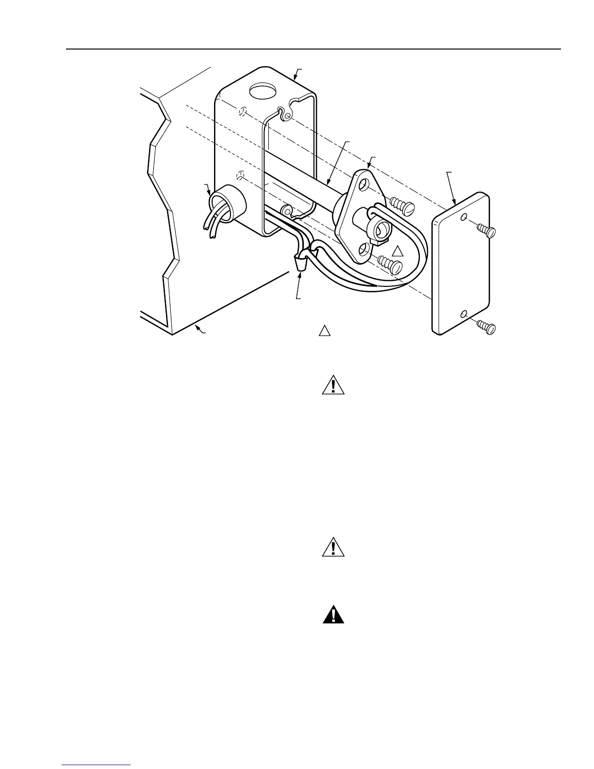
SCREWS NOT PROVIDED.1
1
SENSOR PROBE
SYSTEM DUCT OR PLENUM
FLANGE
STANDARD 2 X 4 (51 X 102)
OUTLET BOX (OPTIONAL)
CONNECTOR
AND
LOCKNUT
BLANK
FACEPLATE
(OPTIONAL)
TO APPROPRIATE
SYSTEM COMPONENTS
(SEE WIRING DIAGRAM)
SENSOR WIRES WITH 2
SOLDERLESS CONNECTORS
M9088
Fig. 8. Mounting C7046C Discharge Air Temperature Sensor in junction box.
Wiring
IMPORTANT
Failure to follow these wiring practices can introduce
electrical interference (noise) that can cause erratic
system operation:
a. Keep wiring at least one foot away from large
inductive loads such as motors, line starters,
lighting ballasts, and large power distribution
panels.
b. Shielded cable is required in installations where
these guidelines cannot be met.
c. Ground shield only to grounded controller case.
IMPORTANT
Minimize erratic temperature readings from a
sensor to assure proper operation by following
these wiring practices:
a. Route temperature sensor wiring away from
building power wiring, control contactors and
light dimming circuits, electric motors and
welding equipment.
b. Make good physical wiring connections to assure
good electrical connections.
c. Make sure that building earth ground connections
are not intermittent or missing.
d. Mount sensor only in recommended environment.
e. Use shielded cable to reduce interference if
rerouting of sensor wiring is not possible.
CAUTION
CAN CAUSE ELECTRICAL SHOCK OR
EQUIPMENT DAMAGE.
Disconnect the power supply before connecting the
wiring.
Make sure wiring complies with applicable local
codes, ordinances and regulations.
Connect low voltage wiring from the sensor to the appropriate
system component terminals using solderless connectors as
shown in Fig. 7 and 8.
M7415A, M8405A Damper Actuators
CAUTION
CAN CAUSE ELECTRICAL SHOCK OR
EQUIPMENT DAMAGE.
Disconnect power supply before connecting wiring.
WARNING
CAN CAUSE PERSONAL INJURY.
Do not remove end covers from actuator; spring
return assembly can release to harm installer.
 Loading...


