EasyManua.ls Logo

Honeywell CLMERL8N User Manual

Honeywell CLMERL8N
34 pages
To Next Page IconTo Next Page
To Previous Page IconTo Previous Page
Page #17 background imageLoading...
Page #17 background image
MERLIN NX ROOM CONTROLLER – INSTALLATION & COMMISSIONING INSTRUCTIONS
17 EN1Z-1035GE51 R0420
OPERATOR INTERFACES
LEDs
The controller features the following LEDs:
T2 R2 T1 R1
!
Fig. 22. Controller LEDs
Table 7. Description of LED behaviors
symbol color function, description
T2 yellow Not used
R2 yellow Not used
T1 yellow
LED indicating transmission of communication
signals via the BACnet MS/TP interface.
R1 yellow
LED indicating reception of communication
signals via the BACnet MS/TP interface.
!
yellow
Status LED indicating firmware problems,
hardware problems, etc. (see Table 8).
green
Power LED indicating firmware problems,
hardware problems, etc. (see Table 8).
Table 8. Status LED and power LED behaviors
# Mode
Status LED
!
(yellow)
Power LED
(green)
1 Power failure Stays OFF Stays OFF
2 Device error* Stays ON Stays ON
3 Firmware download ON/OFF (1 Hz) ON/OFF (1 Hz)
4 No application ON/OFF (0.25 Hz) ON/OFF (0.5 Hz)
5 Broken sensor Stays ON ON/OFF (0.25 Hz)
6 Short-circuiting Stays ON ON/OFF (0.5 Hz)
7 Auto-MAC ON/OFF (0.5 Hz) ON/OFF (1 Hz)
8
Unacknowledged
alarm
ON/OFF (2 Hz) ON/OFF (2 Hz)
9 Normal operation Stays OFF ON/OFF (0.5 Hz)
10
Modbus communi-
cation failure
Stays ON ON/OFF (1 Hz)
*Please return the controller for repair.
The ON/OFF frequencies listed in Table 8 can be converted
from "Hz" (i.e., "ON/OFF per second") to "ON/OFF per
minute" by multiplying them by 60.
Service Button
The Service Button is used to trigger dedicated events.
It is important to distinguish different controller behaviors
which are elicited depending upon whether the controller is
powering up or in normal operation when the Service Button
is pressed. See the following sub-sections.
Pressing Service Button during Power-Up
During controller power-up, pressing the Service Button until
LED behavior #3 (see Table 8) is displayed will reset the
controller to its factory settings, which are as follows:
The application is cleared from the controller.
The MAC address will be set to 0xFF, meaning that the
controller will now look for a new mac address (Auto MAC
will be automatically triggered after controller power-up).
The maxMaster setting will revert to its default value of 35.
The Max info frames will revert to 10.
The device instance will revert to its default of 4194302.
The device name will revert to CLME[ModelName].
The values of automac min_mac and max_mac will be
reset to 1 and maxMaster, respectively.
Pressing Service Button during Normal Operation
During normal operation of the controller, a short press (< 1
sec) of the Service Button will cause a Service Pin Message
(BACnet WhoAmI as a Private Transfer (SerialNo. = 130)) to
be sent.
Question and Answer IconNeed help?

Do you have a question about the Honeywell CLMERL8N and is the answer not in the manual?

Honeywell CLMERL8N Specifications

General IconGeneral
BrandHoneywell
ModelCLMERL8N
CategoryController
LanguageEnglish

Summary

General Information and Pre-Installation Steps

Before Installation Guidelines

Important recommendations and precautions to follow before powering up the unit.

Dimensions and Mounting Options

Terminal Assignment and Connections

Communication Interface Ports

Information on the various communication ports available on the controller.

Power Supply Information and Wiring

General Power Supply Safety and Guidelines

Safety precautions and general information for connecting the controller's power supply.

Electrical Data Specifications

Freely Programmable Applications

Supported Actuators and Sensors

Lists of compatible actuators and sensors for system optimization and control.

Application Function Blocks Overview

Details on Blinds, Light, and other function blocks for implementing control logic.

Manual Control and Command Inputs

Methods for manual blinds positioning and handling application command inputs.

Emergency and Feedback Handling

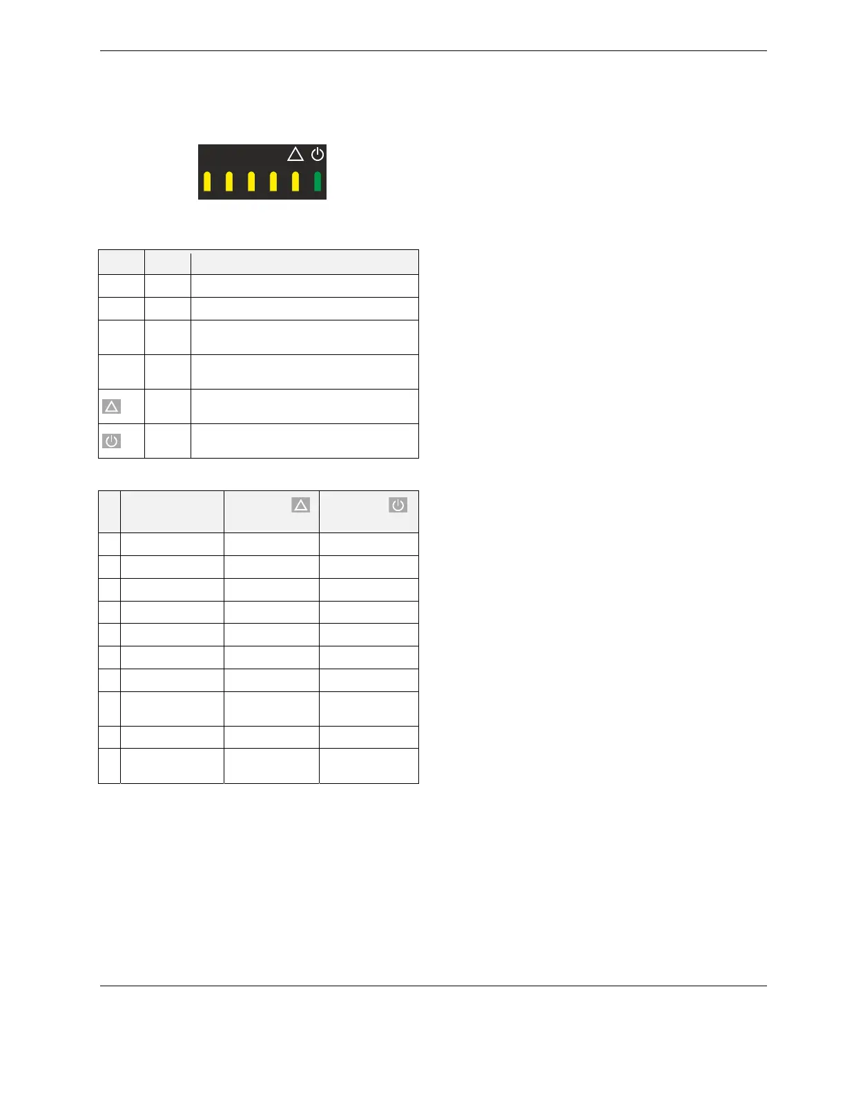
Managing emergency inputs and interpreting feedback signals from function blocks.

Commissioning Parameters and Control Logic

Light Control Functionality Details

Features and operation of the light function block, including manual control methods.

Application Control Logic and Examples

Command and Sensor Logic for Lighting

Using application commands, manual inputs, and sensors for lighting control logic.

Commissioning Procedures

Automatic MAC Addressing on BACnet MS/TP

How the controller automatically assigns MAC addresses on a BACnet MS/TP bus.

Operator Interfaces and Service Button

Service Button Functions

How to use the service button for resets, firmware updates, and operational functions.

Communication Interfaces Overview

BACnet MS/TP and WiFi Connectivity Details

Information on BACnet MS/TP interface, considerations, and WiFi adapter connection.

Specific Communication Interface Details

Modbus Interface Specifications

Modbus Interface Configuration and Compliance

Details on the non-isolated RS485 interface for Modbus master communication.

Sylk Bus Interface

I/O Terminals and Output Specifications

Power Output Terminal Current Limits

Maximum permissible current outputs for power terminals to prevent device damage.

Wall Modules and Display Configuration

Troubleshooting and Support

Troubleshooting and Error Resolution Steps

Steps and advice for diagnosing and resolving common controller issues.

Sensor Characteristics and Accuracy

Related product manuals