MERLIN NX ROOM CONTROLLER – INSTALLATION & COMMISSIONING INSTRUCTIONS
EN1Z-1035GE51 R0420 18
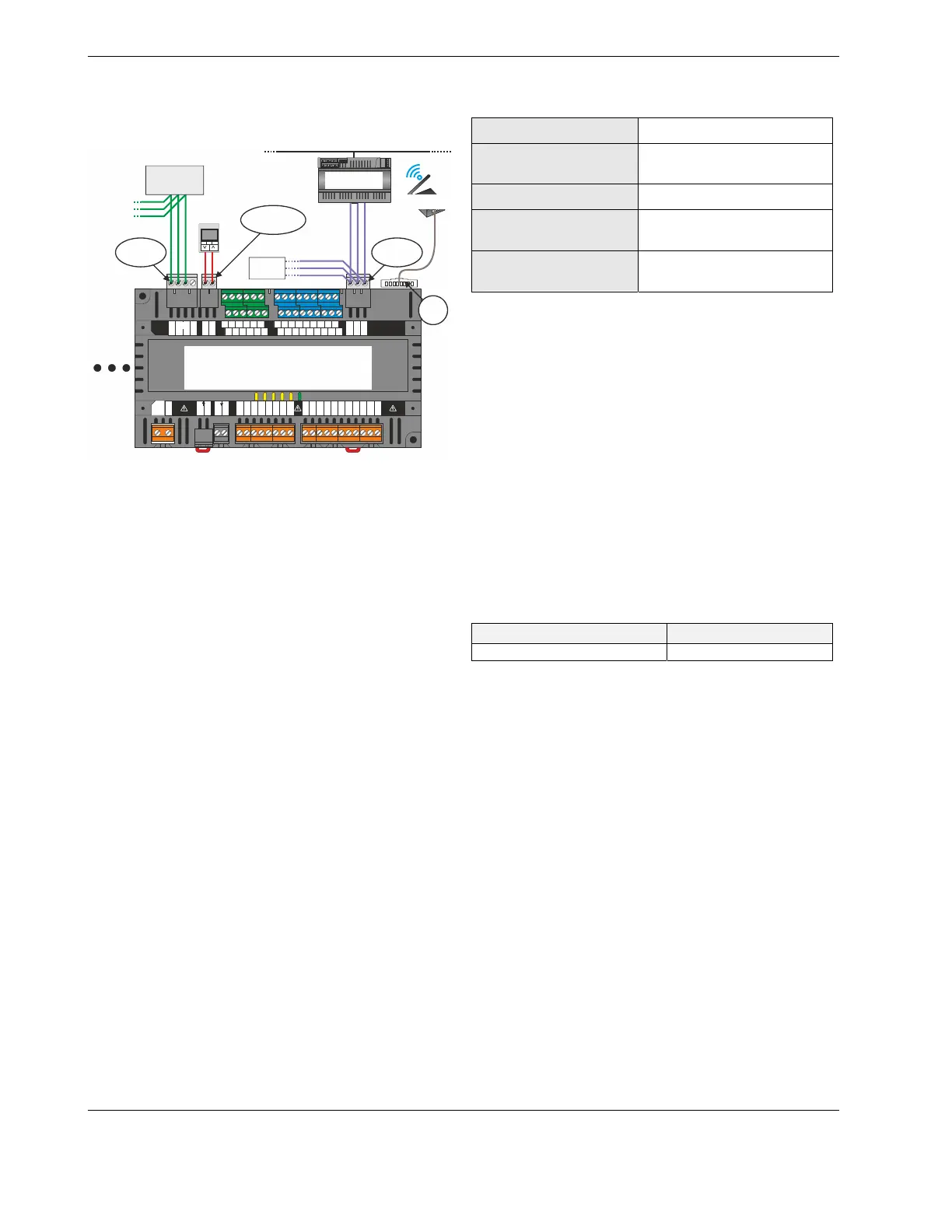
COMMUNICATION INTERFACES
Overview of Interfaces
BACnet IPTCP/IP
BACnet MS/TP
MODBUS
CLCM
TR40x/TR42x
2
N
3
24V~
7
TN
8
T~
9
T01
10
TN
11
T02
12
T03
13
TN
14
T04
15
RC4
16
RO4
17
IN4
18
RN
19
RN
20
IN1
21
RO1
22
IN2
23
RO2
24
IN3
25
RO3
4
24V0
5
24V~
6
24V0
1
L
26
C2+ GND
28
24V~
2927
C2-
WM1
30
WM2
31
3832
AO1
34
AO2
36
AO3
AO4
40
AO5
42
AO6
33
GND
35
24V~
37
GND
39
24V~
41
GND
43
24V~
44
24V~
46
GND
48
UI2
50
UI3
52
GND
54
UI6
56
UI7
58
GND
60
UI10
45
LED
47
UI1
49
GND
51
UI4
53
UI5
55
GND
57
UI8
59
UI9
61
GND
62
C1+
63
C1- GND
64
BACnet MS/TP
SERVICE
RS485-1
INTERF.
RS485-2
INTERF.
SYLK BUS
INTERFACE
PLANT
CONTROLLER
e.g., LIGHT I/O or WALL MODULE
RxxN #62
(MODBUS MASTER)
RxxN #61
(SLAVE)
PREVIOUS
MODBUS
SLAVE
RJ45
BACnet WiFi
ADAPTER
MODBUS
SLAVE
24V0
(GND)
Fig. 23. System overview (example: RLxN)
The TIA/EIA-485 Standard
According to the TIA/EIA-485 standard ("Electrical Charac-
teristics of Generators and Receivers for Use in Balanced
Digital Multipoint Systems"), only one driver communicating
via an RS485 interface may transmit data at a time. Further,
according to U.L. requirements, each RS485 interface may be
loaded with a max. of 32 unit loads. E.g., Honeywell /
CentraLine devices have as little as ¼ unit load each, so that
up to 128 devices can be connected.
BACnet and Modbus connections to the RS485 interfaces
must comply with the aforementioned TIA/EIA-485 standard.
Thus, it is recommended that each end of every bus be
equipped with a termination resistor (not included in ship-
ment) having a resistance equal to the cable impedance
(120 Ω; the wattage should be in the range of 0.25 – 0.5 W).
RS485 systems frequently lack a separate signal ground wire.
However, the laws of physics still require that a solid ground
connection be provided for in order to ensure error-free
communication between drivers and receivers – unless all of
the devices are electrically isolated and no earth grounding
exists.
IMPORTANT
A separate signal ground wire must be used. Failing to
obey this requirement can lead to unpredictable
behavior if other electrically non-isolated devices are
connected and the potential difference is too high.
TIA-EIA 485 Cable Specifications
The following cable specification is valid for all EIA 485 buses
(incl. Modbus and BACnet MS/TP).
Table 9. TIA/EIA 485 cable specifications
max. length
1200 meters (9.6 – 78.8 kbps)*
cable type
twisted pair, shielded (foil or
braided shields are acceptable)
charac. impedance
100…130 Ω
distributed capacitance
between conductors
Less than 100 pF per meter
(30 pF per foot)
distributed cap. between
conductors and shield
Less than 200 pF per meter
(60 pF per foot)
*A higher communication rate (necessitating a shorter max.
length) is possible for Modbus. See section "Modbus
Considerations" on pg. 20.
The following cables fulfill this requirement:
• AWG 18;
• shielded, twisted pair cable J-Y-(St)-Y 4 x 2 x 0.8;
• CAT 5,6,7 cable (use only one single pair for one bus);
• Belden 9842 or 9842NH.
BACnet MS/TP Interface
The controller features an isolated RS485 interface (RS485-
1) suitable for BACnet MS/TP communication:
▪ RLxN: terminals 62, 63, and 64;
▪ RSxN: terminals 40, 41, and 42.
The terminal block containing it is gray. The cable length
affects the communication rate. Table 10 provides a few
examples.
Table 10. Baud rate vs. max. cable length
baud rate max. cable length (L)
9.6, 19.2, 38.4, 57.6, and 76.8 kbps 1200 m
The controller supports auto-baud rate adaption for BACnet
MS/TP communication at all of the aforementioned baud
rates (default: 38.4 kbps).
For information on wire gauge, max. permissible cable length,
possible shielding and grounding requirements, and the max.
number of devices which can be connected to a bus, refer to
standard TIA/EIA-485.
BACnet MS/TP Considerations
The controller communicates via its isolated RS482-1 inter-
face with other BACnet MS/TP-capable devices (e.g., other
room controllers or plant controllers like the EAGLE / Excel
Web II or EAGLEHAWK NX). In doing so, the following con-
siderations should be taken into account.
▪ Max. BACnet MS/TP bus length (= "L" in Fig. 24): See
Table 10.
▪ Twisted-pair cable, e.g.:
- AWG 18;
- J-Y-(St)-Y 4 x 2 x 0.8;
- CAT 5,6,7 cable – use only one single pair for one
bus;
- Belden 9842 or 9842NH);
and daisy-chain topology.
 Loading...