ENI7003R8 KO65 2013
DIGITAL BURNER CONTROLLER
DBC2000 SERIES
1. APPLICATION
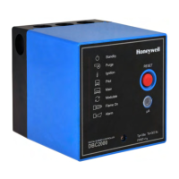
The Honeywell DBC2000 is a microprocessor-based
integrated burner controller for automatically fired
gas, oil or combination fuel industrial single burner
power burner applications. The DBC2000 system
consists of the relay module and wiring subbase.
The DBC2000 Standard Model provides the
minimum requirements to control an industrial
burner system, such as automatic burner
sequencing, flame supervision, system status
indication, system or self-diagnostics and
troubleshooting. The DBC2000 Enhanced Model
includes an integrated Valve Proofing System,
whilst the Ultimate model includes bus
communication on top of this.
The DBC2000 is programmed to provide a level of
safety, functional capability and features beyond
the capacity of conventional controls.
2. FEATURES
•
Employs a plug-in mounting method
• Uses a microprocessor to improve performance
• Status and fault indication by indicator LEDs
• A 4-wire firing rate switching circuit controls an air
damper motor or other auxiliary equipment during
start-up of the burner.
• Safe start check before and during pre-purge
• Dual flame amplifier for UV, IR or flame rod sensor
• Automatic recycle once per 24h of uninterrupted
heat demand.
• Frontal jack plug (Ø 3.5mm) to read the flame
signal with a microampere meter.
• An electrical sub base lock (reset and safety limit
terminals are swapped) to avoid that a Standard
model is used systems wired for an Enhanced or
Ultimate model. The DBC2000 cannot start then.
• Safety shutdown occurs on
- malfunction of the burner controller
- failure to ignite the pilot burner or main burner
- loss of flame during run period
- opening of air flow switch during pre-purge, start-
up, run and post-purge period
- flame signal detection during standby or pre-
purge period
• Integrated Valve Proofing System (Enhanced and
Ultimate models only)
• Remote bus communication (Ultimate model only)
Contents
1. Application 1
2. Features 1
3. Specifications 2
4. Dimensions 5
5. Installation and wiring 6
6. Operation 12
7. Trouble shooting 14
8. Approvals and Maintenance 16
Appendix: VPS calculation and diagrams 18
INSTALLATION INSTRUCTIONS
Important note:
Subject to changes without notice.
Please check our web site
http://hic.emea.honeywell.com
for the most recent version of this document.








 Loading...