ENI7003R8 KO65 2013
6. OPERATION
NORMAL OPERATION
Table 7: Normal operation sequence
Inputs
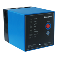
Operation of DBC2000 and device Indicator LED *
HEAT DEMAND SW OFF
AIR FLOW SW OFF
SAFETY LIMIT SW ON
The power supply voltage is applied across Terminal 1 and
2. When no flame signal is present, the combustion airflow
switch is opened (T14=OFF) and safety lockout
circuit is
closed (ON), it is possible to start.
●○○○○○○○
HEAT DEMAND SW ON
START Pos SW ON
The blower is energized (T3). Firing rate goes to PURGE
position. Air flow switch closes (T14=ON) as soon as air flow
is present.
●●○○○○○○
AIR FLOW SW ON
START Pos SW OFF
The pre-purge timer starts counting as soon as PURGE
interlock is closed (T16=ON).
PURGE Pos SW OFF
After the completion of pre-purge timing, firing rate goes to
The ignition wait timer starts counting as soon as the START
position interlock is closed (T17=ON).
START Pos SW ON
After completion of the ignition wait timing, the Ignition
sequence starts. The Ignition transformer is energized. The
Intermittent and Interrupted pilot valve outputs are energized
●○●○○○○○
●○●○○○●○
FLAME ON
When a flame is detected after the ignition trial has ended
(Safety1), the pilot stabilization time starts.
●○○●○○●○
After completion of the pilot-stabilization time, the Main
valves are energized (T7=ON). Note: Enhanced Model: also
(T12=ON).
The Main trial for ignition takes place (Safety2).
●○○○●○●○
After completion of the main trial time, Interrupted pilot valve
is deenergized (T5=OFF). The Main stabilization time starts.
●○○○●○●○
PURGE & START Pos SW
IGNORED
After completion of the main stabilization time, the firing rate
goes to modulation position and releases control to an
external modulation device.
●○○○○●●○
HEAT DEMAND SW OFF
The intermittent pilot valve and main valves are deenergized
(T6=OFF and T7=OFF). Note: Enhanced Model: also
(T12=OFF). Firing rate moves to PURGE position.
The post-purge timing takes place.
●●○○○○○○
FLAME OFF
After the completion of the postpurge time, the blower is
deenergized and firing rate moves to START position.
●○○○○○○○
AIR FLOW SW OFF
After the air flow switch goes OFF, DBC2000E returns to the
STANDBY condition, waiting for the next heat demand.
* For LED indication, ○ means ‘off’, ● means ‘illuminated’.
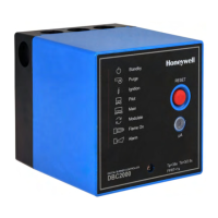
* The LEDs are arranged in the following order: Standby, Purge, Ignition, Pilot, Main, Modulate, Flame and Alarm at the left front
side of the DBC2000.
 Loading...
