EC7823A;RM7823A 7800 SERIES RELAY MODULES
7 66-1086—2
OPERATION
Sequence of Operation
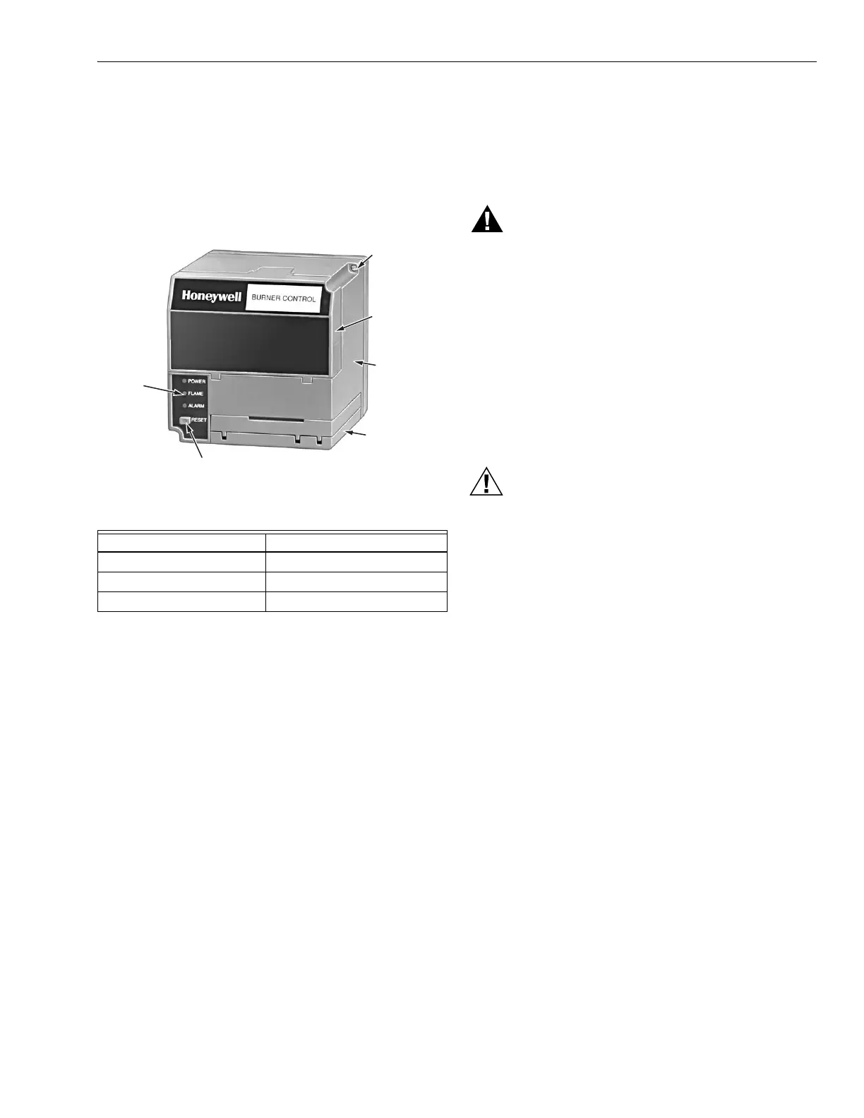
The EC/RM7823A has the following operating sequences,
see Fig.4 and Table 5. The EC/RM7823A LED provide
positive visual indication of the program sequence: POWER,
FLAME and ALARM.
Fig. 4. Sequence status LEDs.
Table 5. LED sequence status display information.
Standby
The EC/RM7823A is ready to respond to sensing of a flame or
flame simulating condition. The green POWER LED blinks
every four seconds, indicating that the relay module is doing
internal hardware checks.
Run
The EC/RM7823A pulls in the internal dpdt relay and turns on
the FLAME LED when a flame or flame simulating condition
exists. The relay module is now in the Run sequence.
Static Checkout
After checking all wiring, perform this checkout before
installing the EC/RM7823A on the subbase. These tests verify
the Q7800 Wiring Subbase is wired correctly, and the external
controllers, limits, interlocks, actuators, valves, transformers,
motors and other devices are operating properly.
WARNING
Explosion and/or Electrical Shock Hazard.
Can cause serious injury, death or equipment
damage.
1. Close all manual fuel shutoff valve(s) before starting
these tests.
2. Use extreme care while testing the system. Line
voltage is present on most terminal connections
when power is on.
3. Open the master switch before installing or
removing a jumper on the subbase.
4. Before continuing to the next test, be sure to
remove test jumper(s) used in the previous test.
5. Replace all limits and interlocks that are not
operating properly. Do not bypass limits and
interlocks.
CAUTION
Equipment Damage Hazard.
Improper testing will cause serious internal
damage.
Do not perform a dielectric test with the EC/RM7823A
installed. Internal surge protectors can break down
and conduct a current. This can cause the
EC/RM7823A to fail the dielectric test or possibly
destroy the internal lightning and high current
protection.
Equipment Recommended
1. Voltmeter (1M ohm/volt minimum sensitivity) set on the
0 to 300 Vac scale.
2. Two jumper wires, no. 14 wire, insulated, 12 in.
(305 mm) long with insulated alligator clips at both ends.
Burner Sequence LED Energized
Standby POWER, FLAME and ALARM.
Run POWER, FLAME and ALARM.
Reset/Alarm Test POWER, FLAME and ALARM.
CAPTIVE
MOUNTING
SCREW
DUST
COVER
RELAY
MODULE
FLAME
AMPLIFIER
RESET PUSHBUTTON
SEQUENCE
STATUS
LEDS
M7889
 Loading...