66-1086—2 G.R. Rev. 12-03 www.honeywell.com
EC7823A;RM7823A 7800 SERIES RELAY MODULES
Automation and Control Solutions
Honeywell International Inc. Honeywell Limited-Honeywell Limitée
1985 Douglas Drive North 35 Dynamic Drive
Golden Valley, MN 55422 Scarborough, Ontario
M1V 4Z9
General Instructions
1. Perform all applicable tests listed in Static Checkout,
Table 6, in the order listed.
2. Make sure all manual fuel shutoff valve(s) are closed.
3. Perform only those tests designated for the specific
EC/RM7823A model being tested.
4. Raise the setpoint of the operating controller to simulate
a call for heat.
5. For each test, open the master switch and install the
jumper wire(s) between the subbase wiring terminals
listed in the Test Jumpers column.
6. Close the master switch before observing operation.
7. Read the voltage between the subbase wiring terminals
listed in the Voltmeter column.
8. If there is no voltage or the operation is abnormal,
check the circuits and external devices as described
in the last column.
9. Check all wiring for correct connections, tight terminal
screws, correct wire, and proper wiring techniques.
Replace all damaged or incorrectly sized wires and
tighten any loose terminal screws.
10. Replace faulty controllers, limits, interlocks, actuators,
valves, transformers, motors and other devices as
required.
11. Make sure normal operation is obtained for each
required test before continuing the checkout.
12. After completing each test, be sure to remove the
test jumper(s).
WARNING
Explosion hazard.
Can cause serious injury or death.
Be sure all manual fuel shutoff valves are closed.
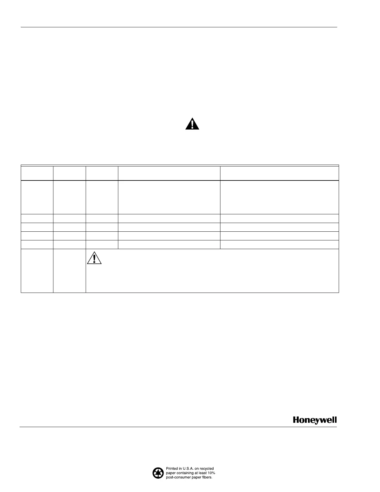
Table 6. Static checkout.
Test
Number
Test
Jumpers Voltmeter Normal Operation
If Operation is Abnormal,
Check the Items Listed Below
1 — L2-3 Line voltage at terminal 3. 1. Master Switch.
2. Power connected to the master switch.
3. Overload protection (fuse, circuit
breaker, etc.) has not opened the power
line.
2 8-9 — Load operation without flame sighting. Load connections to terminals 8 and 9.
3 8-10 — Load operation when flame detected. Load connections to terminals 8 and 10.
4 13-14 — Load operation without flame sighting. Load connections to terminals 13 and 14.
5 13-15 — Load operation when flame detected. Load connections to terminals 13 and 15.
FINAL ALL
CAUTION
Equipment Damage Hazard.
Leaving jumpers in place will damage the equipment.
After completing these tests, open the master switch and remove all test jumpers from the
subbase terminals. Remove any bypass jumpers from limits.
 Loading...