EXCEL 10 W7754K,P,Q,R,S,T,V FCU CONTROLLERS − INSTALLATION INSTRUCTIONS
EN1B-0304GE51 R0916M
2
MOUNTING
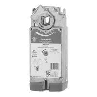
All models have the same dimensions (W x L x H =
110 x 180 x 60 mm) (see Fig. 2) conforming to IP20. With
optional terminal protection cover, width is 130 mm.
130
110
90
59.5
terminal protection
cover (optional)
Fig. 2. Excel 10 W7754 dimensions (in mm)
The unit is suitable for mounting on a standard rail (DIN EN
50022-35 x 7,5), on walls, as well as for installation in wiring
cabinets or fuse boxes.
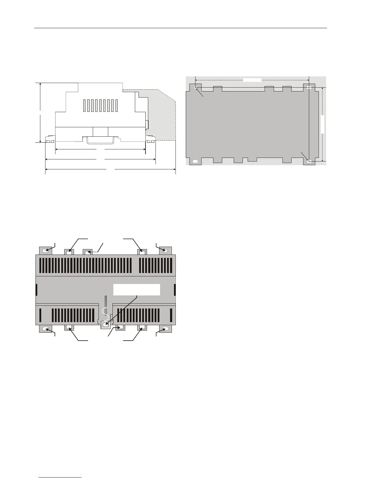
DIN Rail Mounting/Dismounting
EYELETS FOR
CABLE BINDERS
EYELETS FOR
CABLE BINDERS
STIRRUP; PULL DOWN
TO DISMOUNT UNIT
FROM RAIL
SCREWING NOSE
(oval hole)
SCREWING NOSE
(oval hole)
SCREWING NOSE
(oval hole)
SCREWING NOSE
(round hole)
Fig. 3. Housing base (view from below)
The unit can be mounted onto the DIN rail simply by snapping
it into place. It is dismounted by gently pulling the stirrup
located in the base of the housing (see Fig. 3). When
mounted on a DIN rail, the unit must be secured in place with
a stopper to prevent sliding.
Wall Mounting/Dismounting
The unit can be mounted on walls in any desired orientation.
The unit is mounted by inserting 3.5-mm dowel screws
through the corresponding screwing noses.
154 mm
100 mm
oval hole
(4x7 mm)
round hole
(diameter: 4 mm)
Fig. 4. Drilling template (view from above)
After mounting the unit onto the wall, provide for cable access
by snipping out the terminal protection cover's cut-out tabs
and snap it (by hand) into place on the housing. To remove
the cover, place a screwdriver in the leverage slot and pry it
loose.
Terminal Assignment
The unit features two rows of terminal blocks located on one
side for the connection of cables to the relays, inputs, and
outputs as well as for connecting the removable power supply
terminal plug and removable L
ONWORKS terminal plug.
NOTE: All high-voltage terminal blocks are orange-colored.
Depending on the given hardware model, the units have
different power supplies and are equipped with different
numbers of triac outputs, relay outputs, etc. See Table 2 on
page 3.
Every unit is therefore equipped with a terminal assignment
label on the top of the housing (see Fig. 1 on page 1). Unused
terminals are indicated by dotted lines.
NOTE: According to VDE guidelines, it is not allowed to mix
low-voltage and high-voltage signals on the relays.
See also Table 4 on page 6.

 Loading...