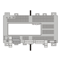
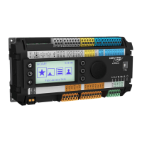
EXCEL 10 W7754K,P,Q,R,S,T,V FCU CONTROLLERS − INSTALLATION INSTRUCTIONS
EN1B-0304GE51 R0916M
3
Table 2. W7754 Controller: Overview of terminals and functions (by model)
term.
#
function
model
K
(1)
P Q R S T V
1+2 Removable plug; receiving/sending data on the LONWORKS network X X X X X X X
3
BINARY INPUT (DI1), configurable (via the LNS plug-in) to read input from, e.g., a hardwired
window contact, occupancy sensor, etc.; suitable for dry contacts, only; max. voltage at open
contact = 5 Vdc
X X X X X X X
4
ANALOG INPUT (AI3), permanently configured to read input from a hardwired wall module's
temperature setpoint adjustment knob; enabled / disabled using the left DIP switch
X X X X X X X
5
ANALOG INPUT (AI2), permanently configured to read input from a hardwired wall module's
room temperature sensor (use NTC20k sensor, only; accuracy [w/o sensor] = 0.5 °C at 25 °C);
enabled / disabled using the left DIP switch
X X X X X X X
6 GND serving terminals 4, 5, 9, 10, and 11 (I/Os for wall module) X X X X X X X
7 GND serving terminal 12 (AO1) -- -- -- X -- X X
8 GND serving terminal 3 (DI1) X X X X X X X
9
BINARY OUTPUT (LED), permanently configured to write output to switch the LED of a hard-
wired wall module ON/OFF; enabled / disabled using the left DIP switch; max. voltage = 5 Vdc;
max. current = 5 mA
X X X X X X X
10
ANALOG INPUT (AI1), permanently configured to read input on whether a hardwired wall
module's 3-speed fan control knob has been set to AUTO, OFF, LOW, MEDIUM, or HIGH and
whether its "occupancy override" button has been pressed; enabled / disabled using the left DIP
switch
X X X X X X X
11
BINARY INPUT (DI2), permanently configured to read input on condition (open/closed) of
window contact; enabled / disabled using the right DIP switch; suitable for dry contacts, only;
max. voltage at open contact = 5 Vdc
X X X X X X X
12
ANALOG OUTPUT (AO1), used (depending upon configuration via the LNS plug-in) to control a
variable speed fan or to control a proportional valve
(2)
or to control a 6-way ball valve
(6)
-- -- -- X -- X X
13+14
A normally-open relay (Rel4), permanently configured to write output to switch a hardwired
electrical reheat coil ON/OFF; switching voltage = 24...230 Vac; switching current = 0.05...10 A
-- X X X -- X X
15 A common terminal for terminals 16, 17, and 18 X X X X X X --
16
(3)
A normally-open relay (Rel3), permanently configured to write output to a hardwired three-speed
fan, setting it to HIGH
X X X X X X --
17
(3)
A normally-open relay (Rel2), permanently configured to write output to a hardwired three-speed
fan, setting it to MEDIUM
X X X X X X --
18
(3)
A normally-open relay (Rel1), permanently configured to write output to a hardwired three-speed
fan, setting it to LOW
X X X X X X --
19
(4)(7)
Triac output (Triac1), perm. configured to write output to OUT1 & close hardwired valve --
(5)
X X X -- X --
20
(4)(7)
Triac output (Triac2), perm. configured to write output to OUT1 & open hardwired valve --
(5)
X X X X X X
21
(4)(7)
Triac output (Triac3), perm. configured to write output to OUT2 & close hardwired valve -- X X X -- X --
22
(4)(7)
Triac output (Triac4), perm. configured to write output to OUT2 & open hardwired valve X X X X X X X
23
(3)(7)
24 VAC common terminal for terminals 19 & 20; internally connected to terminal 24;
W7754T4431, only: internally connected also to terminal 27
X X X X X X X
24
(3)(7)
24 VAC common terminal for terminals 19 & 20; internally connected to terminal 23;
W7754T4431, only: internally connected also to terminal 27
X X X X X X X
25+26
The "N" (25) & "L" (26) power supply terminals (removable plug); W7754Q: 24 VAC (20%),
50/60 Hz; W7754K,P,R,S,T,V: 230 VAC (-15%/+10%), 50/60 Hz
230
VAC
230
VAC
24
VAC
230
VAC
230
VAC
230
VAC
230
VAC
27
(7)
24 VAC / 200 mA auxiliary voltage; internally connected to terminals 23 & 24 -- -- -- -- -- X --
28
(7)
A common terminal for terminal 27; internally connected to terminals 6, 7, & 8 -- -- -- -- -- X --
(1)
The W7754K features an extra socket (2-pin connector located to the left of the terminal blocks) containing an output suitable for attachment to a solid-state relay
(use only Carlo Gavazzi RS1A23D25-P64; max. voltage = 12 VDC; max. current = 12 mA at 10 VDC) for low-voltage PWM control in high-current electrical reheat
applications. To enable it, term. 19 and 20 must be configured (via LNS plug-in) for “Heat” -> “PWM”.
(2)
For AO1 (terminal 12) to be used to control a proportional valve, OUT1 (term. 19 and 20) must be configured (via LNS plug-in) for “PWM”, and the fan must not
be configured for “variable speed fan”.
(3)
If all three relays (term. 16, 17, and 18) are switched OFF, the 3-speed fan will likewise be switched OFF. Switching voltage = 24...230 VAC; switching current =
0.05...3 A (max. 3 A for all three relays together).
(4)
Switching voltage = 230 VAC (W7754K,P,R,S,V) or 24 VAC (W7754Q,T), max. switching current = 0.5 A; max. peak (10 sec) current = 1 A
(5)
For output for low-voltage PWM control of a solid-state relay (W7754K, only) to be used, these terminals must be configured (via LNS plug-in) for “Heat” ->
“PWM”.
(6)
In order for AO1 (terminal 12) to be used to control a 6-way ball valve from Belimo, OUT1 must be configured for "Not USED," OUT2 (term. 21 and 22) must be
configured (via LNS plug-in) for "Changeover Mode" type "Floating Mid," and the fan must not use the analog output (no fan or 1…3-speed fan).
(7)
Total current draw of terminals 19 through 24 and 27 through 28 must not exceed 450 mA.
 Loading...


