3 69-2738EFS—03
Wiring
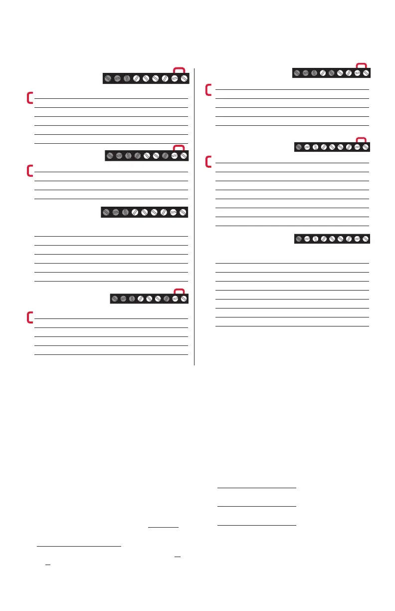
Wiring guide — conventional systems
NOTES
Wire specifications:
Use 18- to 22-gauge thermostat wire.
Shielded cable is not required.
[1] Power supply. Provide disconnect means and
overload protection as required.
[2] Remove jumper for 2-transformer systems.
[4] Common connection must come from cooling
transformer.
[5] In Installer Setup, set system type to Heat Only.
[6] In Installer Setup, set system type to
2Heat/2Cool Conventional.
[7] In Installer Setup, set changeover valve to O
or B.
[8] In Installer Setup, set system type to
2Heat/1Cool Heat Pump.
[9] In Installer Setup, set system type to
2Heat/2Cool Heat Pump.
[10] In Installer Setup, set system type to
3Heat/2Cool Heat Pump.
1H/1C System
(1 transformer)
Rc Power [1]
R [R+Rc joined by jumper]
Y Compressor contactor
C 24VAC common
W Heat relay
G Fan relay
Heat-only System
Rc Power [1]
R [R+Rc joined by jumper]
C 24VAC common
W Heat relay
1H/1C System
(2 transformers)
Rc Power (cooling transformer) [1, 2]
R Power (heating transformer) [1, 2]
Y Compressor contactor
C 24VAC common [4]
W Heat relay
G Fan relay
Heat-only System
with Fan
Rc Power [1]
R [R+Rc joined by jumper]
C 24VAC common
W Heat relay
G Fan relay
Cool-only System
Rc Power [1]
R [R+Rc joined by jumper]
Y Compressor contactor
C 24VAC common
G Fan relay
2H/2C System
(1 transformer) [6]
Rc Power [1]
R [R+Rc joined by jumper]
Y Compressor contactor (stage 1)
C 24VAC common
W Heat relay (stage 1)
G Fan relay
W2 Heat relay (stage 2)
Y2 Compressor contactor (stage 2)
2H/2C System
(2 transformers) [6]
Rc Power (cooling transformer) [1, 2]
R Power (heating transformer) [1, 2]
Y Compressor contactor (stage 1)
C 24VAC common [4]
W Heat relay (stage 1)
G Fan relay
W2 Heat relay (stage 2)
Y2 Compressor contactor (stage 2)
See [notes] below
RcYWG RC
MCR29439
Rc
C
MCR29440
RcWG RC
MCR29444
RcYG RC
MCR29445
RcYWGW2Y2 RC
MCR29446
RcYWG RC
M2944
RcYWGW2Y2 RC
M29447

 Loading...