M3669
R
Rc
W Y G
B D
A C
THERMOSTAT BACK
FOR HIGH EFFICIENCY FURNACE (90%+ AFUE)
SCREW A–OUT 1 TURN
SCREW B–IN
FUEL SWITCH – F POSITION
F
E
FUEL SWITCH
WARM AIR
FURNACE
A–IN
ADJUST SCREWS THROUGH HOLES
TO SELECT OPERATION DESIRED
B–IN
FUEL SWITCH
POSITION
HEATING SYSTEM
ELECTRIC
FURNACE
HOT WATER
BOILER
A–IN
A–OUT
1 TURN
B–IN
B–OUT
1 TURN
E
F
F
ADJUST:
STEP 5
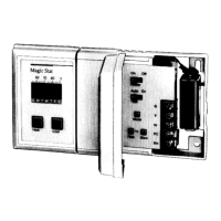
Adjust Fan Operation Switch, As Required
■■ The thermostat fan operation switch, labeled
FUEL SWITCH (see illustration on page 17) is
factory-set in the “F” position. This is the correct
setting for most systems. If your system is an
electric heat system, set the switch to “E.” The
“E” setting will allow the fan to turn on immedi-
ately with the heating or cooling in a system
where the “G” terminal is connected.
16
Adjust System On-Time, As Required
STEP 6
■■ The system on-time is factory-set for a warm
air, gas or oil heating system. If you are installing it
on another type of system, the system on-time
must be adjusted accordingly by setting screws A
and B on the back of the thermostat. Use the
heating system table shown in the illustration on
page 17 as a guide. The system on-time should
be optimized according to the type of system to
minimize room temperature swings. Setting the
screw clockwise means turning the screw
approximately 360° counterclockwise, or about
one complete turn.
In the unlikely event that you want longer furnace
on-time, readjust screws A and/or B as follows:
First, turn both screws
in
completely, then adjust for system type:
• Warm Air Furnace—Set at the Hot Water setting (A - out one turn, B - in).
• Electric Furnace—Leave at the Warm Air Furnace setting (A - in, B - in).
NOTE: This thermostat does not have a
setting for steam/gravity air. Cycles
would not be long enough for accurate
temperature control.
INSTALLATION
IMPORTANT
When using a high efficiency
furnace such as a 90 percent or
greater AFUE (Average Fuel
Utilization Efficiency) unit, adjust
screw A OUT ONE TURN and
screw B IN.
17
 Loading...