24 Installation Instructions MB-Secure 1000/2000/3000/4000/5000/6000
3.10 Lines
All DC connections must be made using shielded telephone cables J-Y(ST)Y / J-H(ST)H. These are installation
cables based on VDE 0815, with a static shield for telephone, measurement and signal transmission. They are
suited for installation in dry and humid plants and factories, with surface or flush mounting, as well as outdoors
using fixed laying. The inner wires are made of copper with a diameter of 0.6 mm or 0.8 mm. Internally, two
cables are stranded into one pair of wires.
3.10.1 Cables to signalling devices
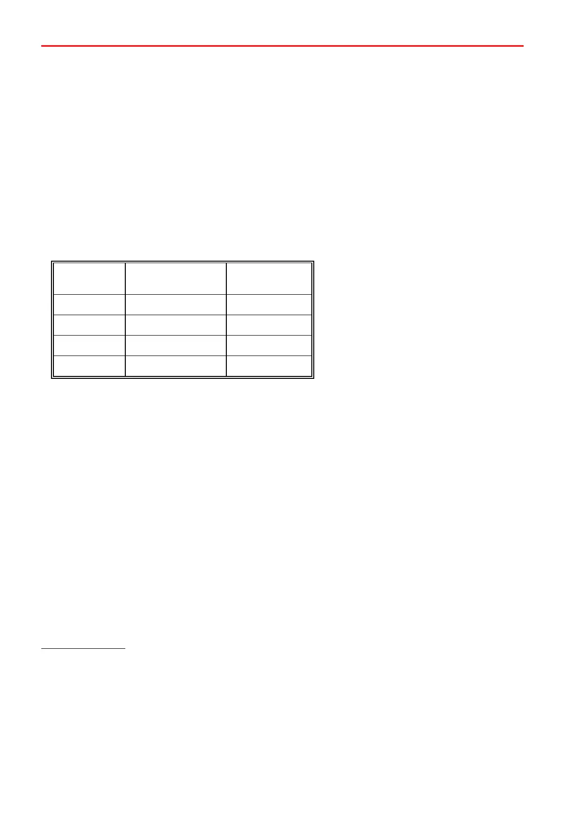
Cable cross-sections in the installation of signalling devices are based on cable length and current consumption.
The maximum total resistance of the cable should be max.3 Ohm.
This gives us the following cable lengths:
(Distance control panel - signalling device)
Number of wires
0.6 mm = 0.28 mm
2
3.10.2 BUS lines
Cables for the 3-wire bus systems have the following functions:
+12 V DC wire → Power supply for BUS users
0 V wire → Return cable/reference potential for BUS users
Data cable / A / B → Data exchange
U
E
cable → Additional cable for supply of power to BUS users with high power consumption
In designing cable cross-section areas for +12 V DC and 0 V, the current consumption of the users connected
must be the starting point. Besides the base power for users, the “switching current” sometimes required, such
as the “all-or-nothing relay” or block magnet release must also be taken into account.
The operating voltage to users must not go below 10 V DC even in the case of emergency power. This means
that a maximum loss of potential of 0.5 V DC (accumulator voltage = 10.5 V DC) is permissible. For modules
with higher current consumption, such as block lock, switch module etc., it is therefore advantageous or
necessary to install a separate cable (U
E
) or a cable with a larger cross-section up to the control panel.
Interference factors
Several influences can have a disruptive effect on bus lines:
- line-related interferences
- capacitive/inductive interferences
- HF interferences
These disruptive influences can be avoided by ensuring the following:
- Do not operate loads with heavy current consumption on the BUS operating voltage, instead feed
the operating voltage via separate supply lines.
 Loading...

