XIO FAMILY OF SPECTRUM SYSTEM REMOTE INPUT/OUTPUT DEVICES
31-00360—01 4
Operating Environment (all models)
Humidity: 5% to 95% Relative Humidity, non-condensing
Operating Temp: -40°F to 158°F (-40° to 70°C)
Storage Temp: -40°F to 158°F (-40° to 70°C)
Operating Voltage (all models)
22VAC - 28VAC, 50/60Hz
Power Supply (all models)
Power and universal inputs are classified as NEC Article
725 Class 2 (power limited)
Power Consumption (per model)
Refer to Table 1 for power consumption per model.
Input/Output Ratings (Class 2)
UNIVERSAL INPUTS:
Thermistor Mode:
Novar refrigeration 2K, useable range -30 to 80°F
(-34 to 27°C)
PRECON Type 2, 10K, useable range 14 to 212°F
(-10 to 100°C) with capability to 375°F (191°C) in
High Temp use
Voltage Mode:
0-10VDC, Input impedance > 5Kohms,
Accuracy = +/- 2% of full scale
Current Mode:
4-20mA with 250 ohm, external, resistor in parallel with
the input terminals, Accuracy = +/-1% of span. Input
supports current loop devices having a loop compli-
ance of 10V or less.
Analog Output Mode:
Minimum output range = 0.1 to 10.5VDC Accuracy =
Not less than +/- 2% of span Resolution = Not less
than 100mV Load Impedance > 2000 ohms
Relay Outputs:
Fused 250 VAC, 5 AMPS, SPDT (Single Pole Double
Throw). Each output has normally closed and nor-
mally open contacts.
NOTE: Use Cooper Bussmann type S500-5A or similar.
See Table 2 for more information.
Current Transformer Inputs:
Range = 0- 5A, Accuracy = +/-5% of span.
Resolution = 100mA
LEDs (all models)
LEDs (models with HOA switches)
LEDS are on solid when relay coil is in its energized
state (actual output state depends on wiring config-
uration)
Safety and Precautions
Observe all national and local electrical codes during
installation.
MOUNTING
The XIO device may be mounted in any orientation on a
panel or a DIN-rail but must be in a position that allows
clearance for wiring or servicing.
Electrical Shock Hazard
Can cause severe injury, death or property
damage.
Disconnect power supply and load power sources
before beginning wiring or making wiring
connections to prevent electrical shock or
equipment damage.
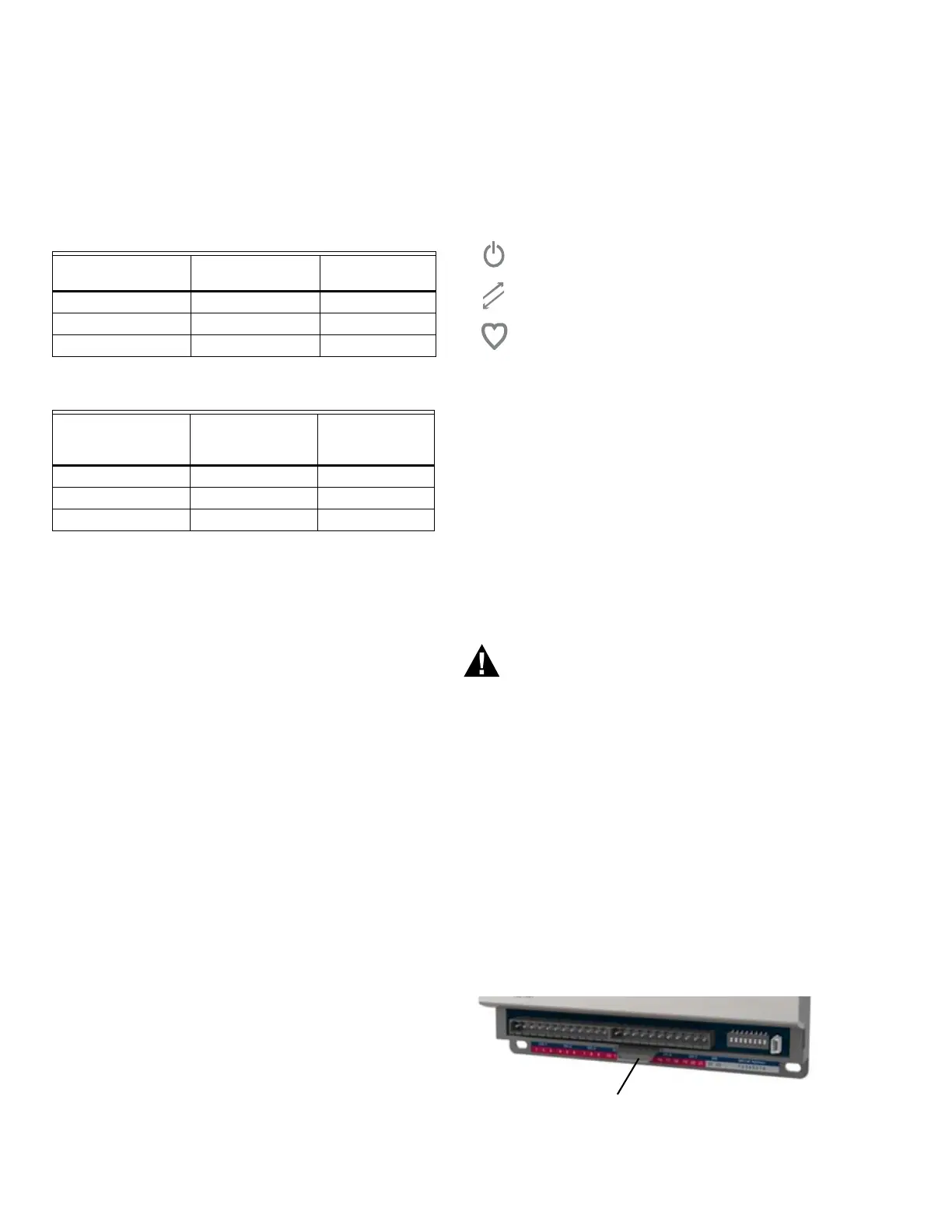
Din Rail Mounting
1. Holding the device with its top tilted in towards the
DIN rail, hook the top ridge of the DIN rail channel on
the back of the controller onto the top of the DIN rail.
2. Gently press down on the bottom half of the XIO
device to allow the DIN latch to engage under the
DIN rail bottom edge.
3. The IO modules must be installed in a concealed
place within HVAC enclosures. The enclosure should
prevent unauthorized physical access to the module.
Fig. 5. XIO device DIN Latch Release.
Table 2. Environmental/Electrical Operating Limits
(Model xio.RIMCT).
Max. Current
per Input (Amps)
Max Number of
CT Inputs in use
Max. Ambient
Temperature
2.5 8 158°F (70°C)
5 4 158°F (70°C)
5 8 140°F (60°C)
Table 3. Environmental/Electrical Operating Limits
(Models xio.ROM, xio.CCM, xio.COM)
Max. Load Current
per Relay Output
(Amps)
Max Number of
Relays in use
Max. Ambient
Temperature
2 8 158°F (70°C)
5 1 158°F (70°C)
5 8 131°F (55°C)
Indicates power (steady on)
Indicates Spectrum connectivity (blinks with
communications)
Indicates module health status (continuous
blink = good health)

 Loading...


