24 PSE Series Instruction Manual — P/N LS10227-000NF-E:B 3/29/2021
Programming Options S1 Global Options DIP Switch
Command Input #1
Power supply Output circuits can be configured to “follow” a sync pattern that is input to Command Input #1 (TB5), either immediately
(Normal Mode), or only after a trigger signal (Sync Input Mode) is applied at Command Input #2 (TB6). In Sync Input Mode an output
circuit will only output the Command Input #1 sync pattern when Command Input #2 is receiving a valid (9V - 32V) trigger signal.
See “Command Input #1 - Normal/Sync Mode of Operation” on page 27 for additional information.
Charger Enable/Disable
The PSE battery charger can be disabled to accommodate an external battery charger, such as the CHG-75 or CHG-120. Setting DIP
switch position 4 to the OFF position will disable the charger. Setting DIP switch position 4 to the ON position will enable the charger. It
should only be disabled if an external battery charger is being used for the PSE.
AC Loss Door Holder Dropout Timer
Any output can be configured as a NAC, aux power, or door closer circuit. Configuring an output circuit as a door closer circuit will pro-
vide a steady 24 VDC to door holders until an alarm condition or an AC fail condition. Upon an alarm condition, power to door holder
circuits will be removed, causing doors to close immediately. During an AC fail condition, the door holder will remain energized until
the programmed AC fail indication delay expires. Programmed delays are only applicable to AC loss conditions. Refer to Table 3.1 for
UL-compliant settings.
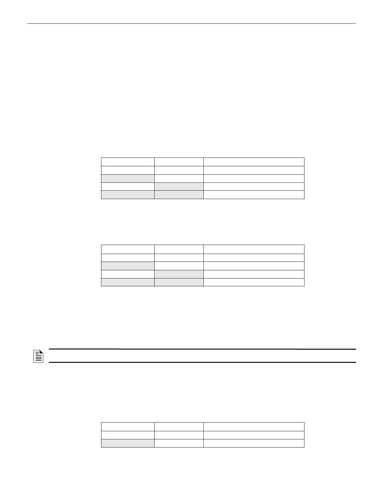
DIP switch positions 5 and 6 are used to select the door holder dropout timer as listed below:
AC Fail Indication Delay
The AC Fail Indication Delay feature provides the option to delay generation of a trouble signal upon the loss of AC power. Refer to
Table 3.1 for UL-compliant settings.
DIP switch positions 7 and 8 are used to select the AC Fail Indication Delay as listed below:
Refer to “AC Trouble Relay” on page 31, for operation of internal NAC trouble relay in response to AC loss.
Special Operating Modes
The power supply can be placed in two special operating modes per settings in Table 3.6. They are Change Output Circuit Configura-
tions and Display Trouble History. Upon completion of either of these two modes, the system must be placed back in normal operating
mode. Note that the current operation of all outputs will not be affected or disturbed while in either of these two special operating modes.
Change Output Circuit Configurations mode:
1. Enter this mode via the setting shown in Table 3.6. Once entered, the Output trouble LEDs will continually flash from right to left to
confirm the PSE is in Change Output Configuration mode.
2. Configure settings on the Output DIP switches as needed (see Note above).
3. Return to Normal Operating mode via either of the two settings shown in Table 3.6. The output trouble LEDs will stop the flash
pattern described above to confirm Normal mode has been restored.
The PSE power supply offers a trouble history mode. To see past troubles on the system, place position 9 to OFF and position 10 to ON.
Refer to Section 4 for descriptions of troubles. Trouble history will be erased upon returning to Normal operating mode.
DIP switch positions 9 and 10 are used to select the type of operating mode as listed below:
Position 5 Position 6 Door holder dropout delay after AC loss
OFF OFF Power does not drop out with AC loss
ON OFF 5 minutes
OFF
ON 60 seconds
ON ON 15 seconds
Table 3.4 Door Holder Dropout Settings
Position 7 Position 8 AC Fail Indication Delay
OFF OFF 30 hours
ON OFF 12 hours
OFF
ON 2 hours
ON ON none
Table 3.5 AC Loss Delay Settings
NOTE: DIP switch settings may be changed to the desired configuration either before or after entering Change Output Circuit
Configurations mode.
Position 9 Position 10 Operating Mode
OFF OFF Normal
ON OFF Change output circuit configurations
Table 3.6 Operating Mode
 Loading...


