PSE Series Instruction Manual — P/N LS10227-000NF-E:B 3/29/2021 37
Appendix B: Application Examples
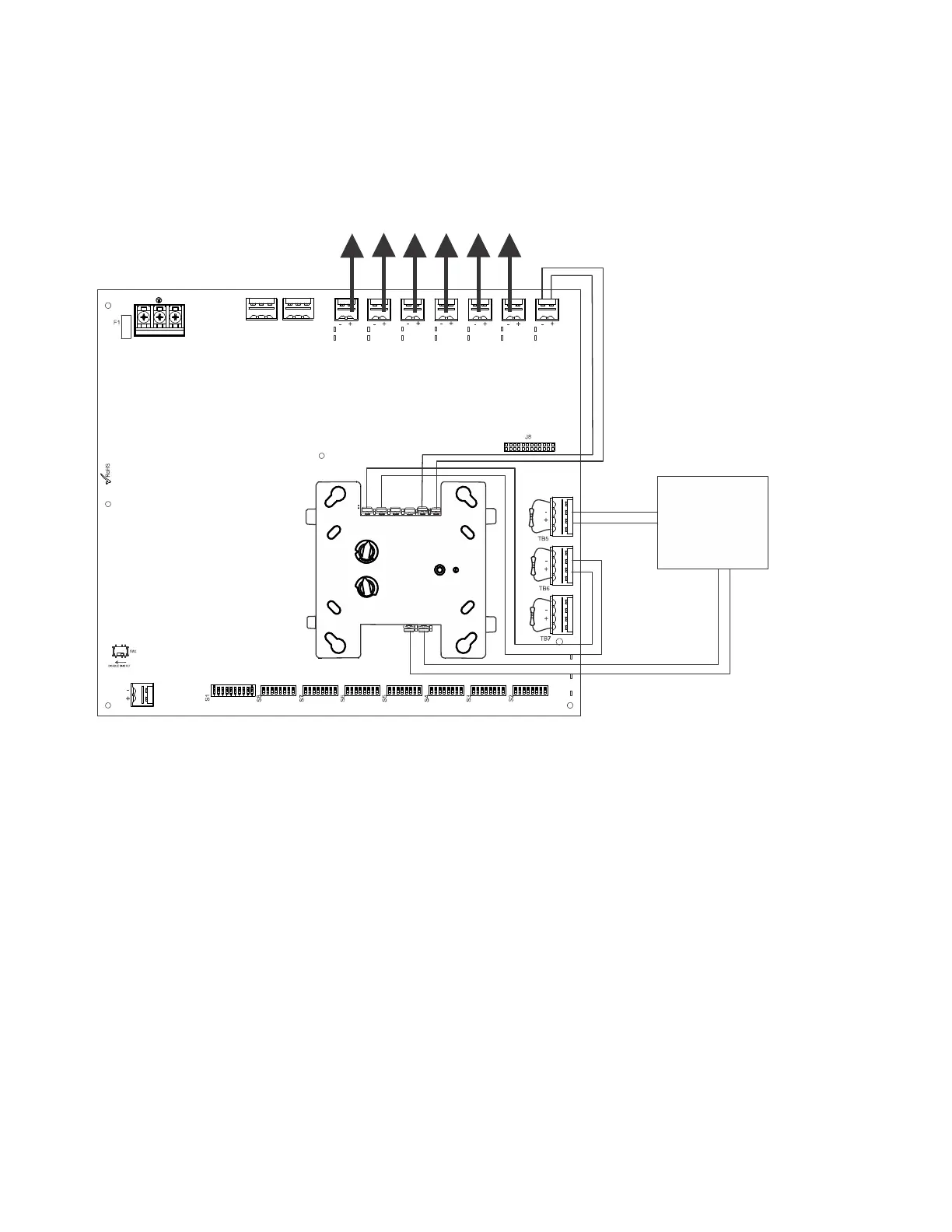
B.1 Controlling NACs For Selective Silence Operation Using a Control Module
In this application, the power supply has been set as a master with synchronized outputs and selective silence (see DIP switch settings
and Selective Silence Operation information in Section 3). This application requires Input #1 to be controlled by the FACP. Input #2 is
required for controlling selective silence via a control/relay module, programmed as an alarm output and a silenceable point. Only Mass
Notification, Fire, or combo Mass Notification/Fire NACs are allowed in this configuration. The control module can be powered by one
of the PSE output circuits, configured as aux power (24VDC).
The following notes apply to Figure B.1.
When the PSE power supply is in an inactive state (FACP NAC not active), a trouble on the NAC circuit will result in an open circuit
condition on the FACP (monitored by End-of-Line Resistor across TB5, Terminals 1 and 4). As an alternative, the trouble contacts at
TB1 of the power supply can also be used for limited trouble monitoring excluding Selective Silence output faults. Refer to Section 5 for
more information.
• Refer to Section 3 for instructions on setting the DIP switches.
• Selective Silence output faults are only reported via Command Input #1 (not Command Input #2).
• Wire NACs as shown on page 13.
• Do not loop wires under screw terminals. Break wires to maintain proper supervision.
• An End-of-Line Resistor must be installed across all input circuits, Terminals 1 and 4, for control module wiring supervision (the
ELR value is dependent on the module/FACP employed).
• For a list of compatible devices, refer to the Notifier Device Compatibility Document #15378.
• Refer to the SLC Wiring Manual for more information.
NO NC C NO NC C
TB4
TB15
T
B
2
T
B
1
T
B
1
3
T
B
1
2
T
B
1
1
T
B
1
0
T
B
9
T
B
8
T1
T11
T2
T10
T3
T9
T4
T8
T5
T7
T6
Figure B.1 Controlling Multiple Outputs with One Input
Control Module*
SLC
*If the SLC device does not match
the one in this figure, refer to the
SLC manual wiring conversion
charts for legacy and newer ver-
sions of the modules.
NAC Output Circuits
24VDC power output
NAC
FACP
 Loading...


