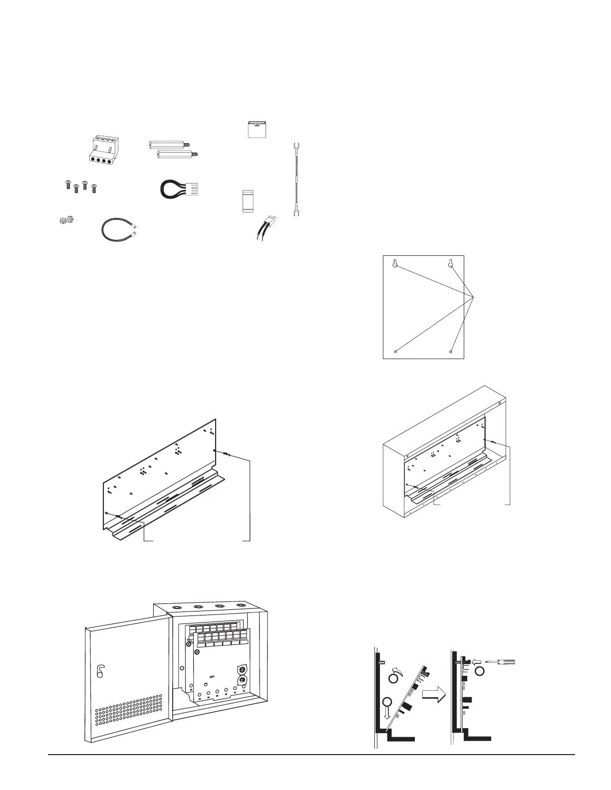
INCLUDED:
Shipped on Board:
(1) Small shunt in A/B select position
(Shipped in Class B position, remove shunt for Class A)
(6) Large shunts on Enable Power Supply Monitors
(6) Large shunts on Disable Short Circuit Protection
(3) Large shunts on Sync Generator
N500-79-00 2 I56-1805-019
The front XP6-C module positions of each chassis are offset below the rear
XP6-C module positions so that all of the status indicators are visible.
Cabinets
A BB-25, CAB-3 Series or CAB-4 Series cabinet will house the CHS-6 chassis
with up to six XP6-C modules installed on it. Refer to cabinet installation
documents for dimensions and installation instructions.
The BB-XP cabinet houses one or two XP6-C modules on the internal chassis
that is part of the cabinet. Refer to cabinet installation documents for dimen-
sions and installation instructions.
INSTALLATION STEPS
1. Cabinet Mounting
In a clean, dry area, mount the backbox using the four holes provided in
the back surface of the cabinet (Figure 3).
2. Chassis Installation
The CHS-6 chassis is mounted in the BB-25, CAB-3 Series or CAB-4 Se-
ries cabinet. It is shipped with two self-threading screws, which are used
to fasten the chassis to the back wall of the cabinet (see Figure 4).
FIGURE 3: TYPICAL MOUNTING HOLE LOCATIONS
BACKBOX
MOUNTING
HOLES
C0235-00
FIGURE 4: MOUNTING THE CHS-6 CHASSIS
MOUNT WITH
SELF-THREADING SCREWS
TO BACK OF CABINET
C0236-00
The BB-XP cabinet comes with the chassis already installed, so no mounting
is necessary.
3. Module Installation
There are two methods for installing a module in the rear position of a
chassis. Method one is for installation of a rear module only, when no
module will be installed in front of it. Refer to Figure 5 for instructions.
Method two is for installation of a rear module when another module
will be installed in the chassis position in front of it. Refer to Figures 6a
and 6b for method two. All necessary screws and standoffs are supplied
with the modules.
FIGURE 5: INSTALLATION OF REAR MODULE ONLY, METHOD ONE
2
3
1
C0237-00
(7) 1×4 Terminal Blocks (2) 1
1
/4″ (32mm) Stand offs
(15) Large Shunts
(4) Machine Screws (5) Short Power Supply Jumpers
(2) Small Shunts
(2) Nuts
(2) EOL Relay Connector
Assemblies
(6) 47k Ohm End of
Line Resistors
(1) Long Power Supply Jumper
C0202-01
COMPATIBILITY REQUIREMENTS
To ensure proper operation, this module shall be connected to a compatible
Notifier system control panel.
COMPONENTS
Following are descriptions of the XP6-C mounting frameworks. There are two
mounting options for XP6-C modules:
• Up to six XP6-C modules can be installed on a CHS-6 in a CAB-3 Series,
CAB-4 Series, or BB-25 cabinet.
• One or two XP6-C modules can be installed in a BB-XP cabi-net.
Chassis
The CHS-6 chassis is used to mount XP6-C modules in a BB-25 CAB-3 or
CAB-4 Series cabinet. It accommodates up to six XP6-C modules in a single
cabinet row three modules wide and two modules deep.
FIGURE 1: CHS-6 CHASSIS
MOUNT WITH
SELF-THREADING SCREWS
C0236-01
The BB-XP cabinet has a built-in chassis that will accommodate one or two
XP6-C modules.
FIGURE 2: BB-XP CABINET
0
1
2
3
4
5
6
7
8
9
0
7
8
6
5
4
3
2
1
9
10
11
12
13
14
15
BASE ADDRESS
ADDRESS
DISABLE
NONE
ONE
TWO
THREE
0
1
2
3
4
5
6
7
8
9
0
7
8
6
5
4
3
2
1
9
10
11
12
13
14
15
BASE ADDRESS
ADDRESS
DISABLE
NONE
ONE
TWO
THREE
C0234-00

 Loading...