N500-78-00 4 I56-1804-012
©2014 Notifier
FCC STATEMENT
This device complies with part 15 of the FCC Rules. Operation is subject to the following two conditions: (1) This device may not cause harmful interference, and (2) this device must
accept any interference received, including interference that may cause undesired operation.
NOTE: This equipment has been tested and found to comply with the limits for a Class B digital device, pursuant to Part 15 of the FCC Rules. These limits are designed to provide
reasonable protection against harmful interference in a residential installation. This equipment generates, uses and can radiate radio frequency energy and, if not installed and used
in accordance with the instructions, may cause harmful interference to radio communications. However, there is no guarantee that interference will not occur in a particular instal
-
lation. If this equipment does cause harmful interference to radio or television reception, which can be determined by turning the equipment off and on, the user is encouraged to
try to correct the interference by one or more of the following measures:
– Reorient or relocate the receiving antenna.
– Increase the separation between the equipment and receiver.
– Connect the equipment into an outlet on a circuit different from that to which the receiver is connected.
– Consult the dealer or an experienced radio/TV technician for help.
NOTES:
• The relay contacts on the XP6-R may be connected to either a power-
limited or non power-limited source, this wiring must remain separated
by at least 1/4˝ (6.35 mm) from all power-limited wiring.
• Power-limited circuits must employ type FPL, FPLR, or FPLP cable as
required by Article 760 of the NEC.
• For easier wiring, assign all power-limited wiring to one side rather than
alternating with non power-limited.
0
1
2
3
4
5
6
7
8
9
0
7
8
6
5
4
3
2
1
9
10
11
12
13
14
15
N.C.
N.O.
COMMON
ADDRESS 5
N.C.
N.O.
COMMON
ADDRESS 4
N.C.
N.O.
COMMON
ADDRESS 3
N.C.
N.O.
COMMON
ADDRESS 2
N.C.
N.O.
COMMON
ADDRESS 1
N.C.
N.O.
COMMON
ADDRESS 0
– +
SLC
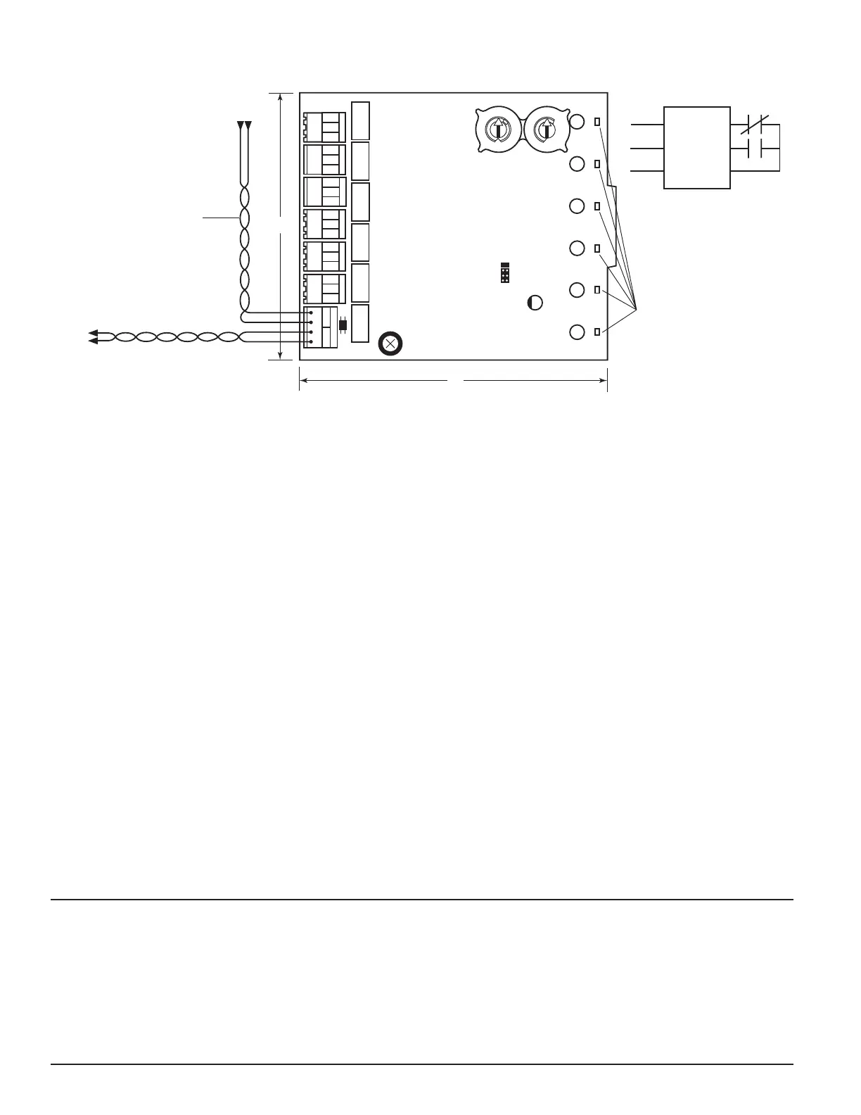
BASE ADDRESS
ADDRESS
DISABLE
NONE
ONE
TWO
THREE
6.8"
5.8"
FROM PANEL
OR PREVIOUS DEVICE
SIGNAL LINE CIRCUIT (SLC)
32 VDC MAX.
SEE PANEL INSTRUCTION
MANUAL FOR
WIRE REQUIREMENTS
TO NEXT
DEVICE
–
+
–
+
–
+
NC
NO
COMMON
RELAY CONNECTIONS
STATUS
INDICATORS
FIGURE 7. WIRING AND PROGRAMMING THE XP6-R MODULE:
C0250-02
PROGRAMMING
The XP6-R module operates with the following Fire Alarm Control Panels:
• AM2020/AFP1010
• AFP-200
• AFP-300/AFP-400
• System 5000 with AIM-200
• AFC-600
• NFS-640
• NFS-3030
The modules are programmed as FRM-1 modules in each system according to
the programming instructions in the appropriate FACP manual.

 Loading...