a The S8910U and the original control lockout times are different. The S8910U lockout time is within the design
tolerance lockout time of the original control.
b The lockout time of the S8910U is shorter than the original control. Be sure to observe the appliance operation
under a variety of input conditions to assure reliable operation.
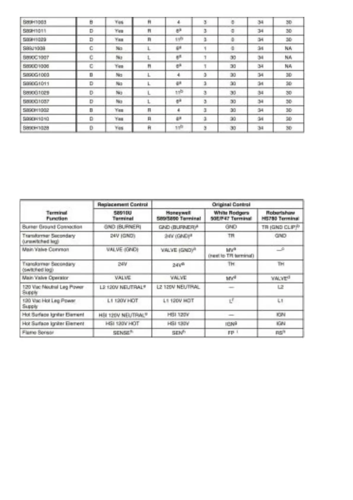
Table 5. Replacement Wiring Terminals.
a Remove quick-connect and replace with the included 1/4 in. quick-connect.
b Use green adapter cable (provided) to connect S8910U GND (BURNER) terminal to chassis ground.
c Do not use the S8910U VALVE (GND) terminal. VALVE (GND) and 24V (GND) are interconnected in the appliance
wiring.
d Remove quick-connect and replace with the included 3/16 in. quick-connect.
e Do not use this terminal if model being replaced does not have 120V neutral power supply connection.
f Use the black wire on the included adapter cable.
g Use the orange wire on the included adapter cable.
h On remote sense models, remove jumper quick-connect from S8910U sense terminal, cut jumper wire at circuit
board and discard. On local sense models, leave black jumper connected.
i Remove jumper from S8910U sense terminal, cut jumper wire at circuit board and discard.

 Loading...


