EasyManua.ls Logo

Honeywell SLATE User Manual

Honeywell SLATE
24 pages
To Next Page IconTo Next Page
To Previous Page IconTo Previous Page
Page #20 background imageLoading...
Page #20 background image
20 32-00006—03
Type T thermocouple
microVolts Degrees C
-5000.000 -166.012
-4200.000 -130.434
-3100.000 -89.867
-1600.000 -43.103
500.000 13.280
3100.000 74.769
6500.000 146.427
10900.000 230.361
16500.000 328.408
20800.000 399.315
Recommended Grounding Practices
Use an Earth ground or a signal ground as described below.
Earth ground (Base, Rectification Flame Amp
Module, other modules optional)
1. Use to provide a connection between the base and the
control panel of the equipment. Earth ground must be capable
of conducting enough current to blow the breaker in the event
of an internal short circuit.
2. Use wide straps or brackets to provide minimum length,
maximum surface area ground conductors. If a leadwire is
required, use 14 AWG copper wire.
3. Make sure that mechanically tightened joints along the ground
path are free of nonconductive coatings and protected against
corrosion on mating surfaces.
Signal ground
Note the 18V system ground is not electrically connected to earth
ground. Follow local codes and appliance recommendations to
determine if this should be connected to earth ground.
Question and Answer IconNeed help?

Do you have a question about the Honeywell SLATE and is the answer not in the manual?

Honeywell SLATE Specifications

General IconGeneral
ModelSLATE
CategoryControl Unit
ManufacturerHoneywell
Memory2 GB RAM
Communication ProtocolsBluetooth, Wi-Fi
InputsTouchscreen
OutputsAudio
DisplayTouchscreen
Operating SystemAndroid
Storage16GB
ConnectivityBluetooth, Wi-Fi, NFC
Barcode ScanningOptional 1D/2D barcode scanner

Summary

Application Overview

Key Features

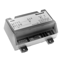
Lists the capabilities and functions of the SLATE Fuel Air Ratio module, including actuator control and communication.

Safety and Specifications

Safety Features and Technical Specifications

Outlines safety features like fail-safe feedback and password protection, followed by technical specifications.

Principal Technical Features

Module Indicators

LED Array and Display Meanings

Explains the function of LEDs on the module for status indication and terminal states.

Module Controls

Select and Reset Button Functions

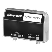
Details the function of Select and Reset buttons and provides essential installation warnings and steps.

Wiring Installation

Wiring Safety and Procedures

Provides critical safety warnings and procedural steps for wiring the module, emphasizing power disconnection and compliance.

Important Notices and Warnings

FCC Compliance and Hazards

Contains important notices about radio frequency energy, FCC compliance, and fire/explosion hazards during installation.

Terminal Pinout and Ratings

Basic Cell Function Specifications

Complex Function Specifications

Frequency and PWM Function Specifications

Sensor and Wiring Recommendations

Sensor Selection Guide

Provides guidance on selecting sensors based on application requirements and performance.

Wire Size and Part Number Guide

Lists recommended wire sizes and corresponding part numbers for various applications and terminals.

Thermocouple Temperature Data

Type J Thermocouple Conversions

Displays microVolt to Degree Celsius conversion values for Type J thermocouples.

Type K Thermocouple Conversions

Displays microVolt to Degree Celsius conversion values for Type K thermocouples.

Thermocouple and Grounding

Type T Thermocouple Conversions

Provides microVolt to Degree Celsius conversion values for Type T thermocouples.

Grounding Practices

Details grounding practices, including earth ground and signal ground, for system safety and performance.

Wire Routing and Length Guidelines

Related product manuals