OPERATOR MANUAL // SECTION 2
INSTALLATION
HONEYWELL 17
2.2.4 Wiring the Detector Module.
a. Insert the cables into the metal enclosure base through one of the
conduit openings. Refer to Figure 6.
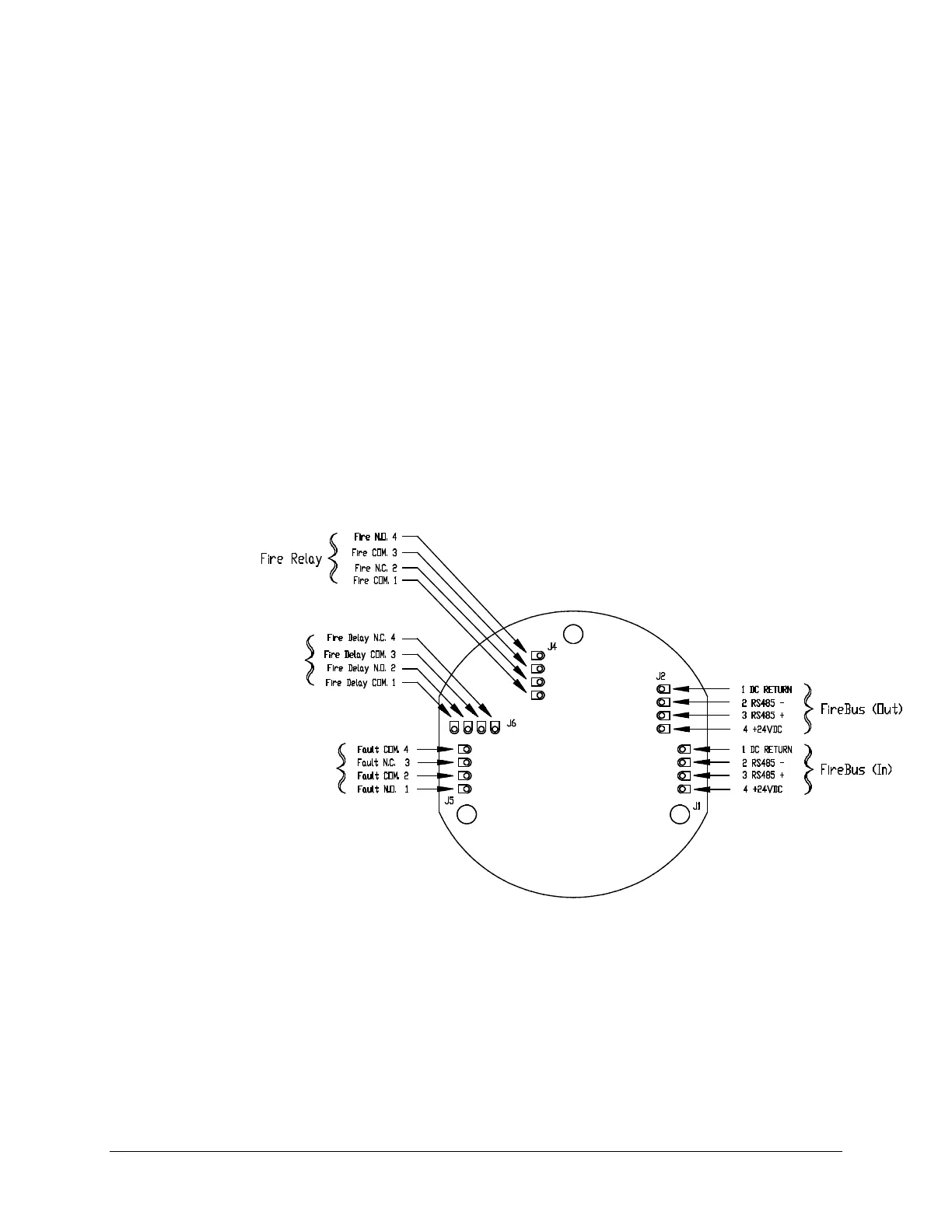
b. Connect the 24 Volt DC power supply wires to pins 1 (-) and 4 (+) of the
J1 or J2 connector, observing the correct polarity. Refer to Figure 2.
Firmly tighten down the two slotted screws with a small screwdriver
taking care not to over-tighten the screws.
Pins 2 and 3 of the J1 and J2 connectors are the RS-485 interface used only for
downloading the FirePic from the Detector’s non-volatile memory, or for viewing
the Tri-Mode Plot. It is recommended to wire pins 2 and 3 to a separate junction
box and properly identify them for future use. A color-coded, multi-connector,
shielded, UL-rated cable with 18 to 24-gauge wire is recommended for
connecting to J1 or J2. The following color-coding is suggested as a guideline:
Pin 1 Pin 2 Pin 3 Pin 4
Black Green or Blue White or Yellow Red
DC Return ( - ) RS-485( - ) RS-485( + ) +24 VDC Power ( + )
* Fault relay is shown in the energized condition
during normal operation (No Fault).
Figure 2: Model SS4-AS/-AS2 Detector Wiring
(Bottom View of SS4-AS/-AS2 Detector Module)
 Loading...