OPERATOR MANUAL // SECTION 4
DETECTOR CONNECTIONS & SWITCH OPTIONS
HONEYWELL 25
SECTION 4
DETECTOR CONNECTIONS & SWITCH OPTIONS
4.1 Detector Connections
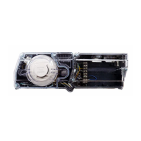
TABLE 1: Stand-Alone Model SS4-A/-A2 Detector
Connectors - Pinouts
J1: DETECTOR INPUT POWER
PIN
1 DC Return ( - )
2 RS-485 Connection to an optional interface unit for
viewing FirePic and TriMode Plot.
3 RS-485 Connection to an optional interface unit for viewing
FirePic and TriMode Plot.
4 Power (+24 Volts DC)
J2: DETECTOR POWER OUT
PIN
1 DC Return ( - )
2 RS-485 Connection to an optional interface unit for viewing
FirePic and TriMode Plot.
3 RS-485 Connection to an optional interface unit for viewing
FirePic and TriMode Plot.
4 Power (+24 Volts DC)
J4: FIRE RELAY
PIN
1 Fire Relay Common
2 Fire Relay Normally Closed
3 Fire Relay Common
4 Fire Relay Normally Open
J5: FAULT RELAY (Energized) J6: FIRE VERIFY RELAY
PIN PIN
1 Fault Relay Normally Open 1 Verify Relay Common
2 Fault Relay Common 2 Verify Relay Normally Open
3 Fault Relay Normally Closed 3 Verify Relay Common
4 Fault Relay Common 4 Verify Relay Normally Closed
 Loading...