69-1598
2
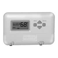
T8034C HEATING/COOLING THERMOSTATS
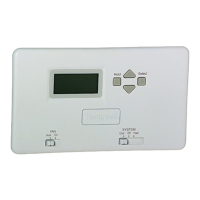
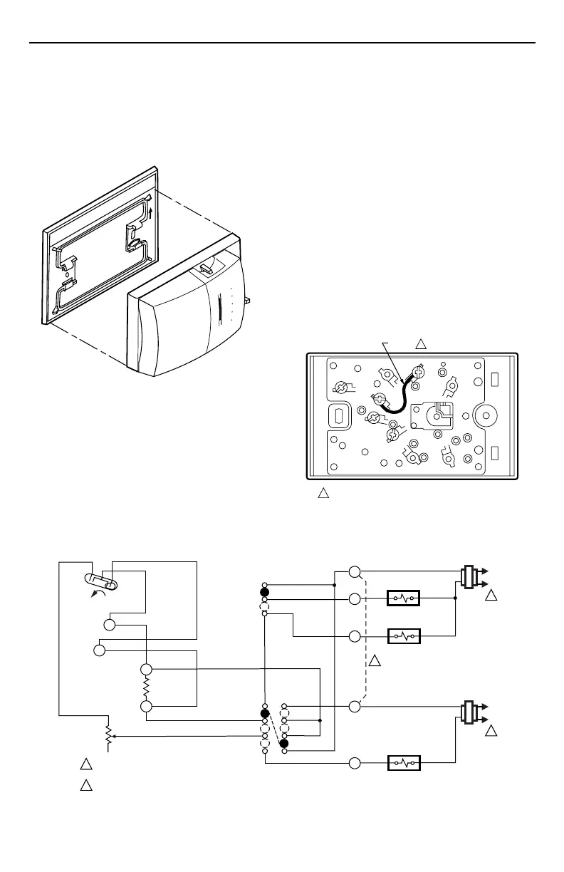
If the 200581 Horizontal Wallplate is used, align the
thermostat and wallplate (see Fig. 2) and press firmly
together until the wallplate snaps in place; then wire and
mount the thermostat.
If the 193121A Mounting Plate Assembly is used, review
the instructions provided with the assembly before wiring
and mounting the thermostat.
H
ea
t
O
ff
C
o
o
l
O
n
F
A
N
Auto
U
P
M20287
90
80
70
60
Fig. 2. Mount the T8034C Thermostat
on 200581 Wallplate.
IMPORTANT
An incorrectly leveled thermostat causes
inaccurate temperature control.
To wire and mount thermostat:
1. In replacement applications, check the existing
thermostat wires for cracked or frayed insulation.
Replace any wires in poor condition. If the wire is
plastered into the wall, make a hole next to the wires
and loosen the wires so that they can be pushed
back into the wall later.
2. In new installations, run wiring (if necessary) to the
thermostat location.
3. Connect the wires to the terminals on the back of
the thermostat. See Fig. 3. For internal schematic
and typical hookup diagram, see Fig. 4 through 9.
4. Remove the thermostat cover by pulling outward on
the right edge of cover until it snaps free of the
thermostat base. Carefully remove and discard the
foam plastic shipping insert that protects the switch
and bimetal assembly during shipping.
5. Set the adjustable heat anticipator indicator to match
the current draw of the primary heating control (see
Heat Anticipator Setting).
6. Push excess wire back through the hole and plug
any opening with insulation to prevent drafts that
may affect thermostat performance.
7. Loosely fasten the thermostat (with wallplate, if
applicable) to the wall or outlet box with a screw
through the left mounting hole. Adjust the thermostat
so that it is approximately level and fasten the
second screw through the right mounting hole. Do
not tighten.
8. For optimum performance, level the thermostat
using a spirit level or plumb line. Tighten the
mounting screws.
9. Replace the thermostat cover.
RC
Y
G
RH
W
JUMPER
1
1 JUMPER NOT SUPPLIED WITH THERMOSTAT.
M2330
Fig. 3. When using T8034C with R
H
and R
C
terminals in single transformer system,
jumper R
H
, R
C
terminals.
H1
TEMP. FALL
C1
L1
(HOT)
L2
1
1
2
2
POWER SUPPLY. PROVIDE DISCONNECT MEANS AND
OVERLOAD PROTECTION AS REQUIRED.
JUMPER RC, RH TERMINALS FOR SINGLE TRANSFORMER SYSTEM.
HEAT RELAY
FAN RELAY
FAN SWITCH
ON
AUTO
COOL
OFF
HEAT
COOL
OFF
HEAT
SYSTEM
SWITCH
C1
ANTICIPATOR
H1
ANTICIPATOR
M1142A
W
Y
G
RC
RH
L1
(HOT)
L2
1
COMPRESSOR
CONTACTOR
Fig. 4. Internal schematic and typical hookup for T8034C in heating-cooling system
with separate heating-cooling transformers or single transformer.
 Loading...