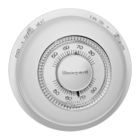
T87F THERMOSTATS
60-2222—3 4
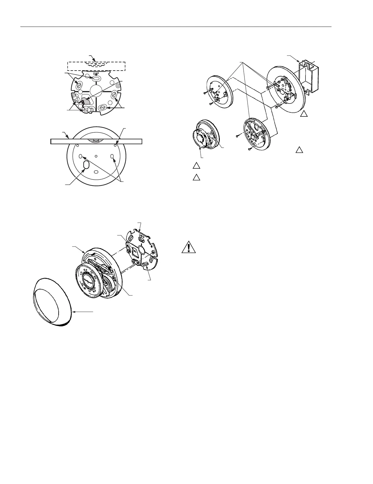
Fig. 1. Level 104456B, 137421A,B,D Wallplates.
Fig. 2. Mount T87F, 104456B Wallplate.
Fig. 3. Mount T87F, Q539 Subbase or 137421 Wallplate to
outlet box.
WIRING
CAUTION
Voltage Hazard.
Can cause electrical shock or equipment damage.
Disconnect power before beginning installation.
IMPORTANT
All wiring must comply with local electrical codes and
ordinances.
The T87F may be used in most 2- or 3-wire, spst or spdt, 24
Vac to 30 Vac heating systems controlled by a low voltage
thermostat. The following wiring diagrams represent typical
applications.
SPIRIT
LEVEL
LEVELING
POSTS (2)
MOUNTING
SLOTS
SPIRIT LEVEL
37421A,B,D WALLPLATE
MOUNTING
SLOTS
BE SURE WAL
HOLE IS
PLUGGED
MOUNTING
SLOTS
TERMINAL
SCREWS
M20772
OPENING FOR
THERMOSTAT
WIRING
T87F
THERMOSTAT
COVER RING
M2077
THERMOSTA
COVER RING
MOUNTING
SLOTS (4)
THERMOSTAT
CABLE OPENING
104456B WALLPLATE
OUTLET BOX
127293
COVER RING
Q539 SUBBASE
M2077
THERMOSTAT
CABLE
ENTRANCE
HOLES
137421
WALLPLATE
CAPTIVE
MOUNTING
SCREWS (3)
T87F
1
1
2
2
IF OUTLET BOX IS HORIZONTAL, MOUNT COVER RING IN POSITIO
SHOWN, BUT FASTEN WITH SCREWS THROUGH "A".
USE 137421A,B WALLPLATE FOR HEAT OR COOL APPLICATIONS
WITHOUT SWITCHING. USE Q539 SUBBASE FOR HEAT OR COOL
APPLICATIONS WITH SWITCHING.
 Loading...