VB6 SERIES 6-WAY CONTROL BALL VALVES AND ACTUATORS - INSTALLATION INSTRUCTIONS
5 Printed in USA 31-00380M-02
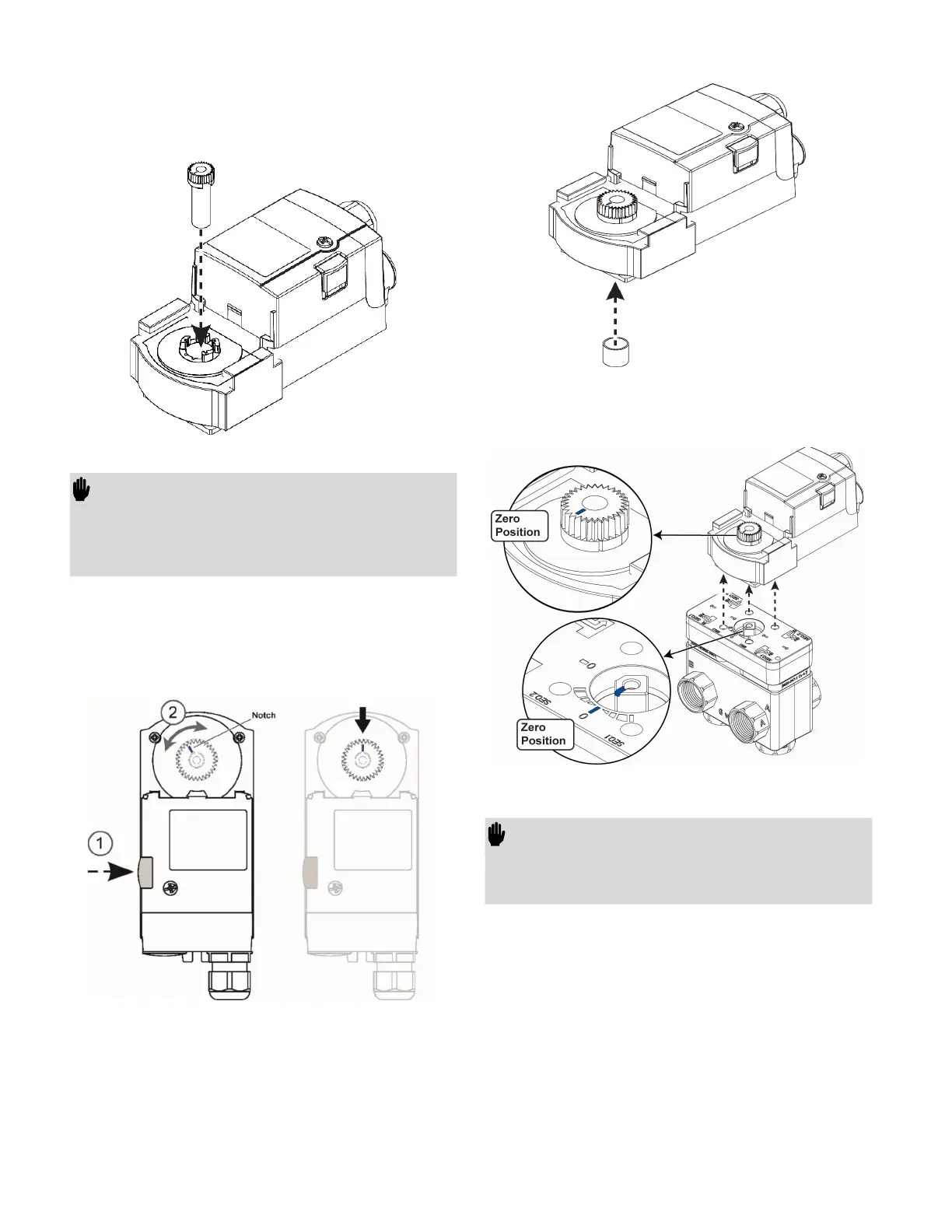
3. Insert the Stem adapter into the Actuator
output hub (Stem adapter and Output hub
are keyed so they can be assembled in one
way only).
Figure 6. Assembly of Stem adapter
IMPORTANT:
To prevent equipment damage, you must
remove power or set the function selection
switch to the “Service/Off” position before
manual adjustment.
4. Press and hold the Declutch button to permit
rotation of the Stem adapter to any position.
Rotate the Stem adapter, so that the notch on
the Stem adapter points as shown in figure
below.
Figure 7. Adjusting the Stem adapter to zero position
5. Slide the Brass sleeve over the end of the
Stem adapter as shown in figure below.
Figure 8. Assembly of Brass sleeve
6. Place the actuator assembly on the Valve
body as shown in below figure.
Figure 9. Assembly on the Valve body.
IMPORTANT:
The only possible way that the valve stem and
actuator Stem adapter can be assembled
together is with both in the Zero position.
7. Insert the Screw (M4) and Washer (supplied
with package) into the linkage shaft and
tighten the screw (1.8 -2.5 Nm) to firmly
assemble the actuator with Valve body. See
figure below.
 Loading...