VB6 SERIES 6-WAY CONTROL BALL VALVES AND ACTUATORS - INSTALLATION INSTRUCTIONS
31-00380M-02 Printed in USA 8
Modulating Run Mode
The Modulating Run mode can be used in four different types of control settings:
• 2…10 Vdc
• 0…10 Vdc
• 10…0 Vdc
• 10…2 Vdc
If the function selection switch has been set to one of the four modulating control settings - and if the
actuator is wired correspondingly (see Figure 13) - then as soon as operating power is applied, the
shaft adapter will run first completely counterclockwise and then completely clockwise, after which it
will run according to the control signals applied.
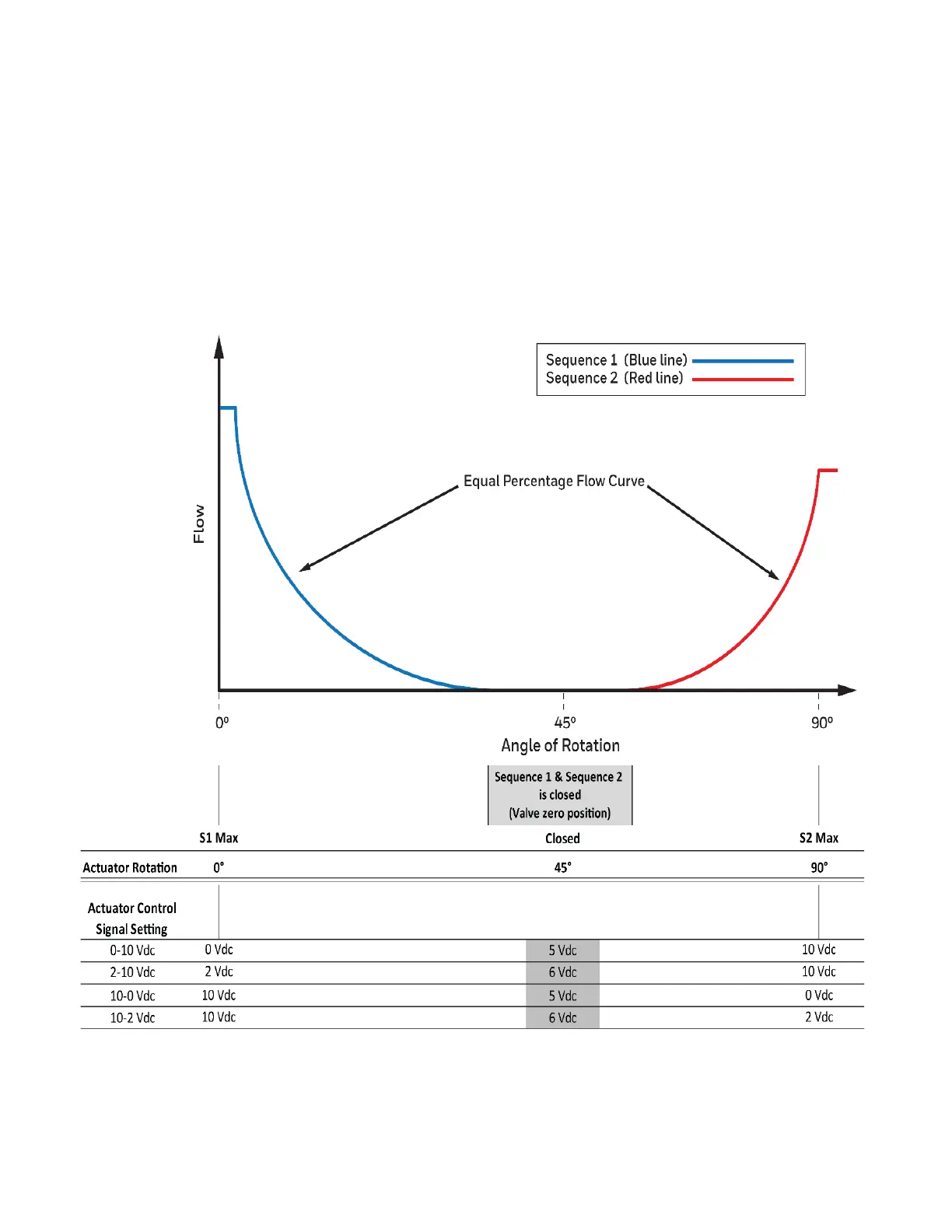
Use the above flow curve with given actuator control signal settings to configure 6-way valve for
Sequence 1 (cooling), Sequence (2), and Off-position. Note that in Figure 13 it is shown how to over-
ride the actuator with a switch on wiring terminal 4 to go to the 50% position. This may also be used to
rotate the valve to the zero (closed) position.
Figure 17. Flow curve with control signal settings
 Loading...