VB6 SERIES 6-WAY CONTROL BALL VALVES AND ACTUATORS - INSTALLATION INSTRUCTIONS
7 Printed in USA 31-00380M-02
Electrical Installation
The most important part of the electrical installa-
tion is the power supply for the actuator.
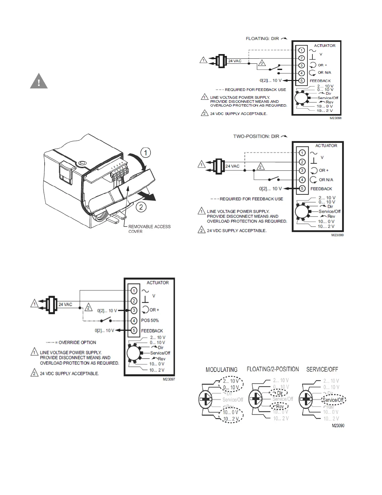
1. Unscrew the actuator wiring cover in order to
access to the terminal block(s) as shown
below.
2. Perform the wiring of actuator using Figure
13 to Figure 15 as per the required
application.
3. If necessary, use the appropriate electrical
cable conduits and cable gland to properly
secure the actuator wiring.
4. Replace the wiring cover once done.
Actuator Run modes
The function selection switch (see Figure 16) can
be used to place the actuator into any one of two
different modes:
• Modulating run mode
• Floating/2-position run mode
• Service/Off mode.
Caution: To avoid personal injury
(electrical shock) and to prevent
equipment damage, before
installation, you must remove power.
Figure 12. Removable Access Cover
Figure 13. MN7510 (Modulating Mode)
Figure 14. MN7510 (Floating Mode)
Figure 15. MN7510 (2-Position Mode).
Figure 16. Function Selection Switch