7-2 www.hp.com Technical Reference Guide
Power and Signal Distribution
Table 7-1 lists the specifications of the external supply.
NOTES:
Total continuous power should not exceed 135 watts. Total surge power (<10 seconds w/duty cycle < 5 %) should not exceed
170 w a t t s .
[1] Using 100 VAC input. The output voltage is allowed to drop to a minimum of 15 VDC during the transient period.
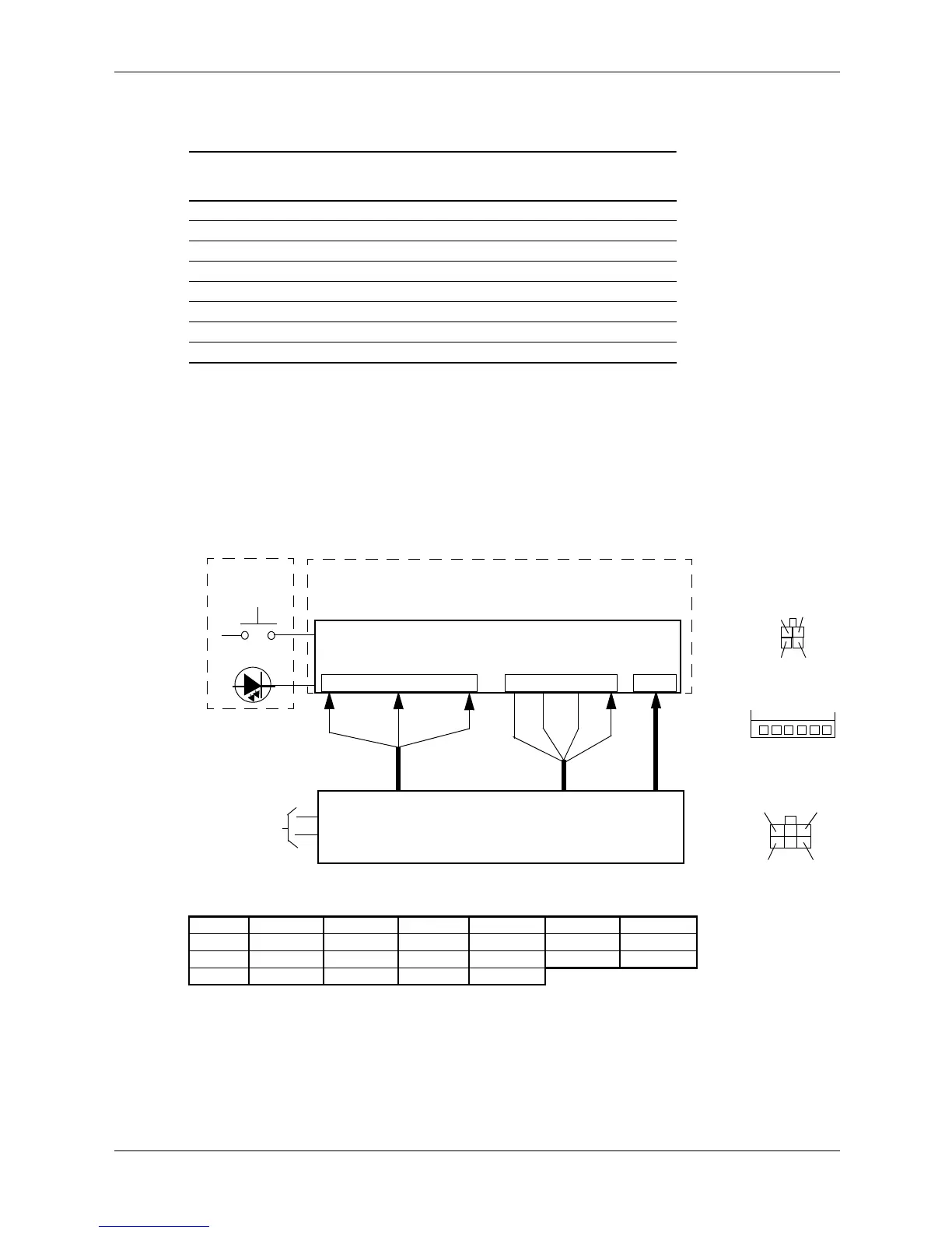
7.3 SFF/CMT Power Distribution
The SFF and CMT form factors use a common power source power supply unit contained within
the system chassis. Figure 7-2 shows the block diagram for power generation in the SFF and
CMT.
NOTES:
Connectors not shown to scale.
All + and
– values are VDC.
RTN = Return (signal ground)
Figure 7-2. SFF/CMT Power Distribution and Cabling, Block Diagram
Table 7-1.
USDT 135-Watt Power Supply Unit Specifications
Parameter
Input Line Voltage Range 90–265 VAC
Line Frequency 47–63 Hz
Input Current, Maximum load @ 90 VAC 2.4 A
Output Voltage 19.5 VDC
Output Current, nominal load 3.5 A
Output Current, maximum load 6.9 A
Output Current, peak load (300 ms max) [1] 9.0 A
Conn Pin 1 Pin 2 Pin 3 Pin 4 Pin 5 Pin 6
P1 RTN RTN –12 V + 12 V m a i n + 12 V m a i n + 12 V s b
P2 FANcmd Fan Speed PS On Pwr Good RTN RTN
P3 RTN RTN +12 Vcpu
+12 Vcpu
System Board
Power On
Power Control Logic, DC/DC Converter
Front Bezel
& Voltage Regulators
Fan
PS
+12 Vcpu
Power Button
Spd
+12 Vmain +12 Vsb
90 - 264 VAC
NOTE: Return (RTN or ground) not shown.
-12 V
P1
On
Pwr
Good
P2 P3
P3
1
2
3
4
1
2
3
4
P2
56
P1
6
1
3
4
Fan
Cmd
Power Supply Unit
 Loading...